
Description
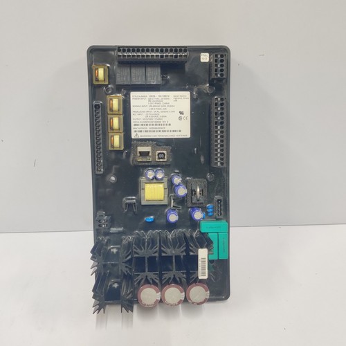
The BASLER DECS-150 (5NS1V) is a robust digital excitation control system designed to provide precise regulation of synchronous generators. By managing the field excitation, this system ensures stable voltage control, reactive power management, and enhanced transient stability for power generation systems. The DECS-150 is widely utilized in industrial and utility-scale power plants, offering advanced protection features and customizable control logic to maintain optimal generator performance under varying load conditions.
Technical Specifications
| Parameter | Description |
| Model | DECS-150 / 5NS1V |
| Manufacturer | BASLER ELECTRIC |
| Function | Digital Excitation Control (Voltage Regulator) |
| Application | Synchronous Generators |
| Input Voltage | 120/240 Vac (sensing) |
| Output Capability | High-precision DC field excitation |
| Weight | Approximately 2.5 kg |
| Origin | USA |
Operational Guidelines & Usage
🔹 Startup Sequence
- Perform a complete check of the field wiring between the DECS-150 and the generator exciter.
- Verify that all sensing and power connections are secure and comply with the wiring diagrams provided by Basler.
- Power on the control unit. The system will undergo an internal power-on self-test (POST).
- Monitor the HMI/front panel; ensure no “Power-up Faults” are present.
- Initiate generator rotation and monitor voltage build-up. The DECS-150 should automatically transition to “Voltage Control Mode” once the generator reaches nominal speed.
🔹 Shutdown Sequence
- Gradually reduce the generator load to idle or disconnected status via the plant control system.
- The DECS-150 will automatically ramp down the field current as the generator speed decreases.
- Once the generator has fully stopped, deactivate the control power supply to the DECS-150.
- Ensure the excitation circuit is safely isolated before performing any maintenance on the exciter components.
🔹 Normal Operational Flow
- The DECS-150 continuously samples the generator’s terminal voltage and frequency.
- It compares these inputs against the setpoint values defined in the system software.
- Using advanced PID control algorithms, it adjusts the firing angle of the internal power bridges to regulate the DC output current.
- It provides real-time protective functions, such as Under-excitation Limiting (UEL) and Over-excitation Limiting (OEL), to keep the generator within safe operating curves.
🔹 Parameter Configuration
- Connect the DECS-150 to a laptop running Basler’s BESTCOMSPlus software.
- Navigate to the “Setup” menu to define system-specific constants, such as generator ratings, CT/PT ratios, and control mode (e.g., AVR or FCR).
- Tune PID gains to match the specific response characteristics of the generator exciter.
- Download the final settings and run a functional test at low load to verify stable voltage output before proceeding to full capacity.
🔹 Mode Switching
- Auto (AVR) Mode: The DECS-150 maintains the generator terminal voltage at the user-defined setpoint.
- Manual (FCR) Mode: The unit acts as a Field Current Regulator, maintaining a constant field current. This is often used during commissioning or when sensing inputs are unreliable.
Common Questions & Answers (Q&A)
💡 Q: What is the purpose of the 5NS1V designation?
A: This code typically denotes a specific hardware configuration, including the power output stage ratings and communication options available for your specific DECS-150 unit. Always check the nameplate against the technical manual to confirm feature compatibility.
💡 Q: How can I troubleshoot an “Excitation Failure” alarm?
A: This alarm usually indicates an issue with the field circuit or the power bridge. Check for open-circuit field wiring, blown excitation fuses, or a failure in the diode bridge. Use the BESTCOMSPlus software to view the specific “Trip” log, which will provide the exact cause of the excitation loss.
💡 Q: Can the DECS-150 operate in parallel with other generators?
A: Yes. The unit supports Droop compensation and Cross-Current compensation to allow for reactive load sharing between generators operating in parallel. These parameters must be calibrated during the system integration phase.
💡 Q: Is the unit user-programmable for specific protective functions?
A: Yes, the DECS-150 includes a suite of configurable protection settings, such as over-voltage, under-voltage, and loss-of-sensing alarms. These can be adjusted via the software to meet the requirements of your specific grid interconnection standards.