
Description
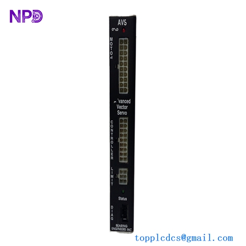
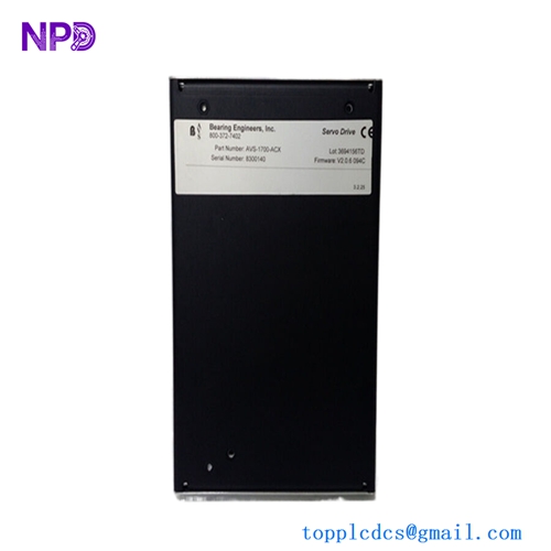
The BEARING ENGINEERS 800‑372‑7402 AVS‑1700‑ACX is an advanced vector servo drive designed to control AC servo or induction motors with high precision in industrial automation systems. It combines torque, speed, and position control in a single compact unit, making it suitable both for single‑axis applications and for integration into multi‑axis motion systems. The drive is intended for panel or cabinet mounting and provides the interface between a machine’s control system (PLC/CNC) and the motor, handling power conversion, feedback processing, and safety functions.
BEARING ENGINEERS 800-372-7402 AVS-1700-ACX
Product description and key parameters
This model belongs to the AVS‑1700 family of “Advanced Vector Servo” drives and typically operates from a three‑phase AC supply, feeding a three‑phase motor. Internally, it uses vector (field‑oriented) control to achieve smooth low‑speed operation and fast dynamic response. Typical characteristics for a drive of this class include:
- Three‑phase AC input (common industrial voltage class, e.g. 230/400/480 V, depending on variant).
- Three‑phase AC output to the motor, sized for medium‑power servo axes.
- Control modes: torque, speed, and position, selectable via parameters.
- Feedback support for incremental encoders or similar devices to close the loop.
- Digital and analog I/O for commands and status (enable, fault, ready, speed reference, etc.).
- Built‑in protections against over‑current, over‑voltage, under‑voltage and over‑temperature.
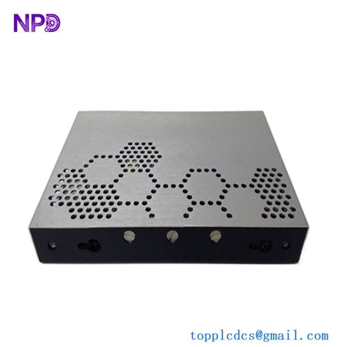
The unit is typically supplied in a metal case with mounting holes, a heat‑sink section, and front/rear connectors for power, motor, feedback, and control wiring.
BEARING ENGINEERS 800-372-7402 AVS-1700-ACX
Datasheet‑style information
A datasheet for the AVS‑1700‑ACX normally covers:
- Electrical ratings: allowable input voltage range, input current, and output continuous/peak current.
- Performance: speed range, maximum speed, speed regulation, basic accuracy and repeatability in position mode.
- Environment: ambient temperature range, cooling method (convection or forced‑air), humidity limits, and enclosure type.
- Interfaces:
- Power terminals for mains and motor.
- Feedback terminals for encoders.
- Control terminals for digital inputs/outputs and analog inputs (for example a 0–10 V or 4–20 mA reference).
- Status indication: LEDs or display showing “ready”, “run”, and “fault” conditions, and a list of standard fault codes.
Even when exact numbers differ by sub‑variant, the AVS‑1700‑ACX is positioned as a high‑performance, vector‑controlled servo drive rather than a simple V/f inverter.
Origin
The AVS‑1700‑ACX is marketed under the Bearing Engineers name. The design and manufacture are aimed at industrial markets in North America and internationally, reflecting typical North‑American industrial practices for panel‑mount servo drives. Actual assembly location can vary by production batch, but the product is intended as an industrial‑grade servo solution rather than a low‑cost hobby drive.
Application fields
The drive is suitable wherever accurate, repeatable motion is required:
- Machine tools: spindle orientation, feed axes, rotary tables.
- Robotics and gantries: X‑Y‑Z or multi‑axis motion for pick‑and‑place and handling.
- Packaging and converting machinery: synchronized axes for cutting, sealing, and web handling.
- Assembly and test equipment: positioning of fixtures, indexing tables, linear slides.
- General automation: pumps, mixers, conveyors that require controlled acceleration, deceleration, and speed or position control.
In many plants, AVS‑series drives are used as replacements or upgrades in existing machines where changing the entire control system is not desirable.
Basic usage instructions
1. Mechanical installation
- Mount the AVS‑1700‑ACX inside an electrical enclosure, using the threaded mounting holes in the case.
- Ensure adequate clearance around the heat‑sink for airflow and access to terminals.
- Observe the manufacturer’s recommended orientation (usually vertical, heat‑sink fins aligned for convection).
2. Power and motor wiring
- Connect the three‑phase AC supply to the designated input terminals, including protective earth.
- Wire the motor phases to the motor output terminals, taking care with cable sizing, shielding where needed, and correct earth bonding.
- Install appropriate upstream over‑current protection (fuses or breaker) in line with the rated input current of the drive.
3. Feedback and control connections
- Connect the motor’s encoder or other feedback device to the feedback connector using shielded cable; keep encoder cables separate from power cables where possible.
- Connect digital inputs (e.g. drive enable, forward/reverse, limit switches, fault reset) from the PLC or control system.
- Connect digital outputs (drive ready, fault) back to the control system for status monitoring.
- If using analog reference for speed or torque, connect the analog signal (commonly 0–10 V) to the analog input and share a common reference ground.
4. Parameter setup and commissioning
- After wiring, power the drive and verify that basic status indicators show “ready” with no faults.
- Enter motor nameplate data (voltage, current, speed, encoder resolution) into the drive parameters.
- Select the desired control mode (speed, torque, or position) and enter limits for speed, torque, acceleration and deceleration.
- Perform initial tests with no load or a light load:
- Check direction of rotation.
- Verify that the actual speed follows the reference.
- Confirm that fault conditions (for example, opening an emergency stop input) stop the motor as expected.
- For position applications, configure homing sequence (limit switch or encoder index) and test move commands to confirm repeatable positioning.
5. Normal operation and maintenance
- During operation, monitor drive status via LEDs or the machine HMI; react promptly to any fault indications.
- Keep the enclosure and heat‑sink clean and unobstructed; remove dust regularly so that cooling performance is not reduced.
- Periodically re‑check terminal tightness (power and control) and inspect cables for mechanical damage or insulation wear.
- When servicing or replacing the drive, always isolate the supply, wait for internal capacitors to discharge, and verify that no hazardous voltage remains before touching terminals.