

Description
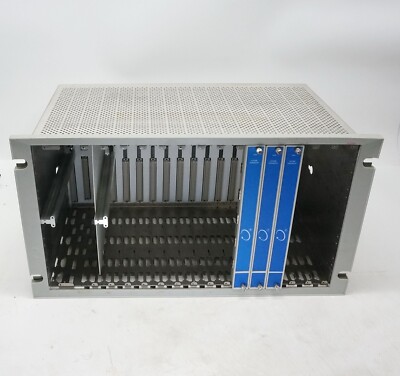
- Model: BENTLY 3500/15 106M1081-01
- Brand: Bently Nevada (USA)
- Series: 3500 Machinery Protection System
- Core Function: Supplies regulated AC power to 3500 monitoring racks
- Product Type: Universal AC Power Input Module
- Key Specs: 85–264 VAC input, 47–63 Hz, half-height rack module
The 106M1081-01 module works together with the Bently Nevada 3500/15 power supply assembly to provide stable rack power for vibration monitoring and machinery protection systems. It is commonly deployed in:
- Steam turbines
- Gas turbines
- Compressors
- Pumps
- Large rotating machinery protection cabinets
A lot of plants still rely on the 3500 platform because replacing an entire protection system usually means:
- New logic validation
- Shutdown approvals
- Rewiring
- SCADA integration work
- Regulatory recertification
That’s why this module often becomes an “A-category” spare during inventory planning.
From a spare-parts strategy perspective:
- Critical sites should keep 1–2 units on-site
- Multi-plant groups can use cross-site shared inventory
- Slow-moving plants may use vendor-managed stock to reduce carrying cost


BENTLY 106M1081-01
Key Technical Specifications
- Product Type: Universal AC Power Input Module
- Compatible System: Bently Nevada 3500 Machinery Protection System
- Input Voltage Range: 85–264 VAC RMS
- Nominal Voltage: 110–220 VAC
- Input Frequency: 47–63 Hz
- Current Consumption: Up to 2.8 A RMS
- Module Design: Half-height rack module
- Mounting Position: Left-side dedicated rack slots
- Operating Temperature: -30 °C to +65 °C
- Storage Temperature: -40 °C to +85 °C
- Humidity Rating: Up to 95% non-condensing
- Protection Features: Overvoltage, short-circuit, and thermal protection
- Weight: Approximately 0.34 kg
- Country of Origin: United States
- System Redundancy Support: Dual power supply redundancy supported
- Hot Replacement Capability: Supported when redundant supply installed
Technical references compiled from industrial inventory listings and 3500-series documentation.
Installation & Configuration Guide
Pre-Installation Preparation (Estimated Time: 10 Minutes)
⚠️ Safety First
- Notify operations and maintenance teams
- Confirm machinery protection bypass procedures
- Switch monitored equipment to safe operating condition
- Disconnect rack power if redundancy is unavailable
- Wait 5 minutes before touching rack components
Required Tools:
- Anti-static wrist strap
- PH1 screwdriver
- Fluke 115 multimeter
- Label markers
- Insulation resistance tester
- Camera or mobile phone
Before removal:
- Export rack configuration
- Photograph rack layout
- Record module slot location
- Check alarm history in System 1 software
One thing engineers sometimes overlook… the 3500 rack may continue running from the backup supply even after the primary module is removed. Always verify actual live voltage before touching terminals.
Removing the Existing Module (Estimated Time: 5 Minutes)
- Remove front protective cover
- Verify backup supply status if redundant power exists
- Disconnect field power safely
- Release module retaining mechanism
- Pull module straight outward
Inspect:
- Rack connector pins
- Burn marks
- Dust accumulation
- Oxidation around power contacts
⚠️ Important:
Do not force the module sideways. The backplane connectors on older 3500 racks can deform if excessive force is applied.
Installing the New Module (Estimated Time: 10 Minutes)
- Wear anti-static protection
- Open original anti-static packaging carefully
- Verify model number and revision
- Inspect connector condition
- Align module with rack guide rails
- Push evenly until fully seated
- Secure retaining hardware
Before power-up:
- Confirm input voltage range
- Verify grounding continuity
- Check redundancy configuration
- Confirm rack fuse condition
Installation checklist:
- Correct slot position
- Module fully inserted
- Ground verified
- Backup supply operational
- No loose hardware inside rack
- Power cabling tightened properly
Power-On & Functional Testing (Estimated Time: 15 Minutes)
Power-up sequence:
- Energize rack power
- Observe front LEDs
- Confirm no fault indicators
- Check System 1 diagnostics
- Verify rack communication stability
- Confirm monitoring channels remain active
Functional validation:
- Verify stable rack voltage
- Confirm communication continuity
- Monitor vibration channel status
- Check alarm relay operation
- Observe temperature rise during runtime
Our incoming QC workflow normally includes:
- Serial number traceability verification
- Packaging inspection
- Connector wear inspection
- Live rack testing using Bently Nevada 3500 test benches
- 24-hour powered runtime verification
- Insulation resistance testing (>10 MΩ at 500 V)
We also document:
- Firmware revision
- Module labels
- Rack communication screenshots
- Thermal condition during testing
Photos and test videos can usually be shared before shipment.
Customer Cases & Industry Applications
Case 1: Gas Turbine Protection Rack Recovery in a Petrochemical Plant
A petrochemical complex in Southeast Asia operated multiple gas compressors protected by Bently Nevada 3500 systems. During routine maintenance, engineers identified intermittent rack power alarms traced to a failing 106M1081-01 module.
The issue became urgent because the affected compressor supported hydrogen circulation. An unexpected shutdown could have halted multiple downstream units.