
Description
Product Core Brief
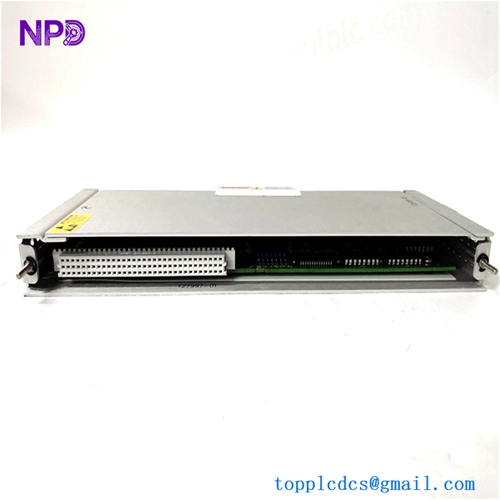
- Model: Bently Nevada 125720-01 (Part of the 3500/32 System)
- Brand: Baker Hughes (formerly GE / Bently Nevada)
- Series: 3500 Machinery Protection System
- Core Function: 4-Channel Relay interface for machinery shutdown and alarm logic.
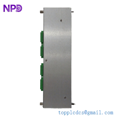
- Type: Relay Module (I/O)
- Key Specs: 4 Independent Relays Single-Pole Double-Throw (SPDT) SIL Compatible
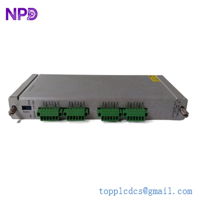
BENTLY 125720-01 3500/32
Key Technical Specifications
- Number of Channels: 4 (Each individually programmable)
- Relay Type: SPDT (Single-Pole, Double-Throw) / Form C
- Contact Ratings: 5 A @ 24 VDC / 250 VAC (Resistive)
- Max Switching Power: 150 W (DC) / 1250 VA (AC)
- Contact Life: 100,000 cycles at rated load
- Response Time: < 10 ms (from alarm to contact change)
- Isolation: 1500 V RMS (Relay to Rack)
- Programming: Via 3500 Rack Configuration Software
- Relay States: Normally De-energized or Normally Energized (selectable)
- Vibration/Shock: Meets standard industrial machinery specifications
Application Scenarios & Pain Points
In high-speed rotating equipment—think steam turbines, large centrifugal compressors, or massive cooling tower fans—the 3500/32 relay module is the “judge, jury, and executioner.” While your vibration monitors (like the 3500/42M) detect the trouble, it’s this relay that physically opens the circuit to the E-Stop or the Fuel Shutoff Valve. If this module fails, you lose the ability to automatically trip a machine during a catastrophic vibration event. I’ve seen a refinery “hope for the best” while waiting for a relay spare, only to have a motor bearing disintegrate and cause $2 million in mechanical damage because the auto-trip failed to fire.
Typical Application Scenarios:
- Critical Machinery Shutdown Wiring the relay contacts into the “Master Trip Solenoid” circuit of a 50MW generator to prevent shaft damage.
- DCS/PLC Alarm Interfacing Providing dry contacts to a plant-wide SCADA system to indicate “Alert” or “Danger” status levels.
- Annunciator Panel Control Driving localized visual and audible alarms in the turbine hall when vibration exceeds ISO standards.
- Redundant Logic Schemes Utilizing “2-out-of-4” voting logic to ensure a single sensor failure doesn’t cause a nuisance trip of a billion-dollar asset.
Case Study: The Nuisance Trip Nightmare
Background: A natural gas pumping station was experiencing “phantom trips” where the turbine would shut down, but the vibration data showed everything was within limits. The Problem: The 125720-01 module installed had a “sticky” relay on Channel 2. Vibration levels were fine, but the physical relay contact was bouncing due to internal spring fatigue, triggering the shutdown circuit. Solution: We supplied a new-in-box 125720-01. Before installation, we verified the “Normally Energized” (fail-safe) logic settings in the 3500 software. Result: The phantom trips stopped immediately. The station manager estimated they saved $40,000 per day in uptime by eliminating the false shutdowns.
Compatible Replacement Models
The 3500/32 has a few variations, specifically regarding the “High Power” vs “Standard” versions.
| Original Model | Replacement Model | Compatibility Level | Key Differences | Change Required |
| 125720-01 | 149986-01 | ✅ Direct | Newer revision, same footprint. | None. Plug and play. |
| 125720-01 | 3500/33 | ⚠️ Software | 16-channel version (High Density). | Major rack re-config & wiring. |
| 125720-01 | 125728-01 | ❌ Incompatible | Output Module for 3500/34. | Different logic processing. |
Integration Note: Bently Nevada modules are “keyed” to specific slots in the 3500 rack. If you are replacing a module and it won’t slide in easily, do not force it. Check the plastic keying headers on the backplane connector. Also, remember that the 125720-01 refers to the main module—if your backplane (I/O module) is damaged, that is a separate part number (usually 125712-01).
Troubleshooting Quick Reference
| Symptom | Potential Cause | Part Correlation | Quick Check | Action |
| “OK” LED Off | Internal Self-Test Fail | ✅ High | Check Rack Configuration Software for error codes. | Replace module. |
| “TX/RX” LED Off | Rack Comm Error | ⚠️ Medium | Check the Rack Interface Module (RIM) status. | Inspect backplane connectors. |
| Relay Won’t Trip | Logic Configuration | ⚠️ Medium | Use “Software Over-ride” to force relay state. | Verify logic voting (1-out-of-2, etc). |
| Relay Stuck Closed | Contact Welding | ✅ High | Disconnect field wires and check continuity. | Replace module (relay is non-serviceable). |
| “CH BYPASS” LED On | Manual Bypass Active | ❌ Low | Check front panel or software “Bypass” switch. | Deactivate Bypass for protection. |
The “Old Engineer” Advice: “Listen, if you’re replacing this module, you absolutely must verify your voting logic. If the rack is set for ‘Normally Energized’ (fail-safe) and you pull the module without putting the rack in Bypass, you are going to trip the machine. It’s a rookie mistake that gets people fired. Bypass the rack, pull the module, swap the DIP switches if applicable, and verify the config before you take it out of Bypass.“