
Description
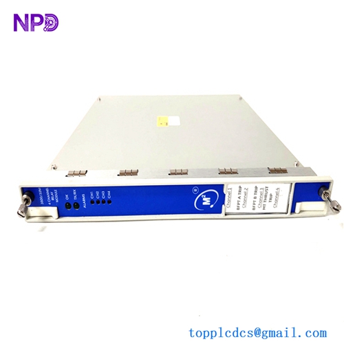
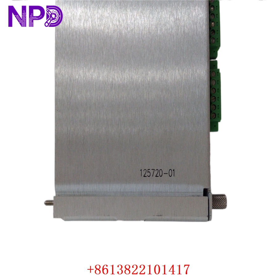
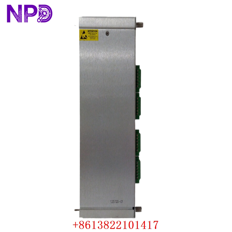
- Model: BENTLY NEVADA 125720-01 (Main board component of the 3500/32 monitoring system)
- Brand: Bently Nevada (USA / Baker Hughes)
- Series: 3500 Machinery Protection System
- Core Function: Four-channel programmable relay module providing discrete contact outputs for machinery trip interlocks
- Condition: Brand New Surplus (Original authentic stock, zero run-time hours, non-refurbished)
- Product Type: 4-Channel Relay Control Module
- Key Specs: Dual-slot design, support for up to 4 independent SPDT relays, backplane logic processing
- Operating Input Voltage: Supplied directly through the 3500 system rack backplane (+5 V DC and +24 V DC rails)
- Power Consumption: 6.0 W maximum internal operational load
- Relay Output Channels: 4 independent Single-Pole Double-Throw (SPDT) Form C relay contacts
- Contact Current Rating: 5 A at 240 V AC / 30 V DC resistive thresholds
- Contact Material: Silver cadmium oxide alloy base (gold-plated options available for low-current applications)
- Isolation Barrier: 1,500 V RMS minimal isolation between relay contacts and internal system logic
- Response Latency: Drive processing signal to contact state change in less than 25 ms
- Operating Temperature: -30°C to +65°C ambient air envelope
- Storage Temperature Envelope: -40°C to +85°C maximum limits
- Humidity Tolerance: 5% to 95% relative humidity (RH, non-condensing)
- Conformal Coating: Standard industrial PCB coating for corrosive atmosphere protection
- Diagnostics: Full onboard hardware watchdog timers and real-time internal relay coil drive checking
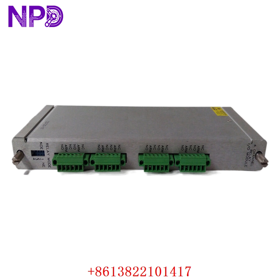
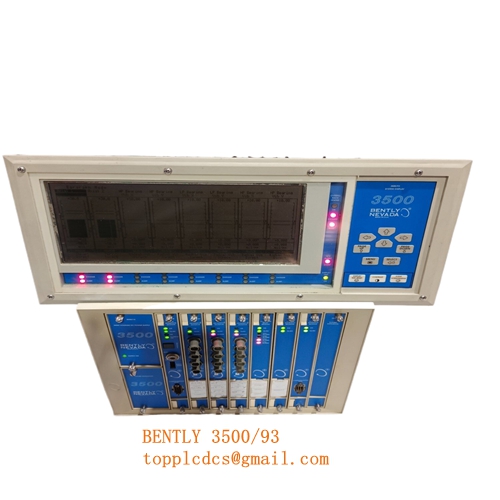
BENTLY 125720-01 3500/32
BENTLY 125720-01 3500/32
BENTLY 125720-01 3500/32
Installation & Configuration Guide
Pre-Installation Setup
⚠️ CRITICAL SAFETY WARNING:
- Coordinate a formal bypass window with the machinery control operators before accessing the active 3500 rack.
- Ensure all automated turbine/compressor emergency trip loops linked to this relay module are placed in manual override mode to prevent an accidental asset trip.
- Verify that the remaining cards in the active 3500 rack are operating cleanly before working on the target slot.
- Use an insulated voltage tester to confirm that no high-voltage external wetting potential is active on the rear terminal block connections.
- Required Tools & Gear:
- Grounded anti-static wrist strap connecting directly to the cabinet steel frame.
- Standard 3.0 mm flathead slot screwdriver for terminal panel retention screws.
- Digital multimeter (such as a Fluke 87V) with thin probe tips.
- Bently Nevada 3500 Rack Configuration Software tool running on a dedicated engineering laptop.
- Handheld camera or phone for documenting rear terminal block wire tagging profiles.
- Backup Procedures:
- Connect your laptop to the 3500/22 Transient Data Interface (TDI) module front USB/serial port, open the configuration software, and save a full upload profile of the existing rack parameters (.wcf file).
- Note the exact slot assignment of the module within the primary chassis framework.
- Document the precise physical position of all hardware configuration jumpers located along the side of the 125720-01 PCB layout.
Old Module Removal
- Engage Rack Bypasses: Activate the software bypasses or use the physical rack key switch to place the target system into “Bypass” mode. This stops the relay output contacts from triggering a machine shutdown while unseating connections.
- Loosen Faceplate Screws: Back out the top and bottom captive screws located on the module front bezel using your flathead screwdriver.
- Eject the Module: Pull the card’s integrated extraction handles outward at the same time to break the friction bond with the heavy backplane edge pins.
- Slide out safely: Draw the card straight forward along its plastic track guides. Hold the assembly by its front panel plate or PCB margins and place it flat on your ESD mat.
New Module Mounting and Configuration
- ESD Mitigation: Keep your grounded wrist strap attached while removing the new module from its silver anti-static shielding package. Do not touch the gold contact traces on the edge connector.
- Hardware Configuration Setup: Look at your reference photos of the old card. Replicate the exact positions of any physical jumper blocks on the new board’s PCB surface. These jumpers set the relay channel operating logic, allowing you to configure each channel independently as either “Normally Energized” or “Normally De-energized.”
- Chassis Alignment: Align the top and bottom edges of the new card with the empty slot track guides in the 3500 rack. Slide the module smoothly backward until the rear interface connector makes initial contact with the backplane pin array.
- Secure Fasteners: Press the card firmly home until the front plate sits flush against the frame margins. Tighten the top and bottom captive securing screws down snug (do not overtighten, roughly 0.6 N·m torque) to maintain a solid frame ground connection.
Post-Installation Verification Checklist
- [ ] Confirm all onboard configuration jumpers match the original card’s settings perfectly.
- [ ] Verify that front panel retaining screws are completely threaded down snug.
- [ ] Check that neighboring monitoring cards in the sub-rack have not been jarred out of place.
- [ ] Ensure that the card is fully seated and the front panel power LED illuminates instantly on initialization.
Power-Up & Loop Commissioning
- Once the card is seated, the 3500 rack backplane supply will automatically energize the card’s internal logic lines.
- Observe the front-facing LED diagnostics assembly array:
- OK (Green): Solid green indicates the module has passed its internal self-test and is operating properly.
- TX/RX (Green): Flashing green indicates active communication traffic with the main rack controller module.
- CH ALARM (Amber): Steady amber means the designated relay channel has been driven into an active trip state by the system logic.
- BYPASS (Amber): Steady amber means the module remains safely bypassed from executing external trip actions.
- Launch the 3500 Rack Configuration Software on your laptop. The software will flag an electronic ID or serial number mismatch code.
- Use the application manager interface to download your archived rack configuration profile straight to the new module’s non-volatile flash memory.
- Take the module out of bypass mode once the system indicates clean status logs across all input channels.
- Run a functional loop test: simulate an over-speed or high-vibration trip threshold from an input monitor card (like a 3500/25 or 3500/42). Verify that the designated relay channel on the 125720-01 module opens or closes smoothly according to your configuration logic, and check that the trip state transfers down to the machine isolation interlocks accurately.
- Once the loop clears and returns to ambient background levels, log the serial number into your plant maintenance tracking database and sign off the card as fully active.
Customer Cases & Industry Applications
Case 1: Gas Turbine Emergency Trip System Restoration
A combined-cycle power station in the Pacific Northwest experienced intermittent fault alarms on its primary gas turbine protection rack. The 3500 system kept reporting communication dropouts from the main relay module handling the mechanical trip-solenoid interlocks. The station operators faced a critical risk: if the relay module failed completely, it could trigger an emergency turbine shutdown, causing up to $150,000 in grid delivery penalties and lost generation revenue.
The plant team was quoted a 14-week factory delivery window for a replacement module. To avoid a forced outage during the summer peak load window, they contacted us to check our ready surplus stock for an 125720-01 module. We retrieved a brand-new surplus card from our warehouse, mounted it onto our 3500 system verification rack, and ran a continuous 24-hour communication and contact cycling stress test. The part was packed securely and sent via express priority courier, reaching the station within 24 hours. The site instrument technicians completed the physical swap, downloaded the configuration profile, and restored full protection system operations overnight without any machine downtime.
Case 2: Refining Center Compressor Rack Maintenance
A large refining center along the Gulf Coast used a Bently Nevada 3500 system to monitor and protect its critical wet gas compressor units. During a routine turnaround inspection, a technician found that an existing 3500/32 relay board had sustained severe internal contact wear over years of operation, causing intermittent resistance fluctuations on its primary output channels.
[Compressor Relay Contact Wear] ──> [Intermittent Resistance Alarms]
                                                │
                ┌───────────────────────────────┴───────────────────────────────┐
                ▼                                                               ▼
  [Option A: Complete Rack Upgrade]                                [Option B: Direct Board Replacement]
  • Cost: High capital expenditure (~$65,000)                      • Cost: ~70% savings vs complete upgrade path
  • Downtime: 3 days of panel rewiring and testing                 • Downtime: Completed in under 20 minutes
  • Execution Risk: High loop recoding workload                    • Execution Risk: Zero wiring adjustments needed
The plant engineering team wanted to avoid an expensive system upgrade since the compressor rack was scheduled for a complete modernization project in four years. They chose to replace the individual card by ordering a new surplus unit from us. We supplied a brand-new 125720-01 module complete with factory conformal coating to resist atmospheric moisture and chemical contaminants. The plant crew installed the replacement card, transferred the existing channel configurations, and verified the loop interlocks in less than twenty minutes. This quick drop-in swap eliminated the resistance fluctuations, maintained safety standards, and avoided an unplanned capital upgrade project.
Frequently Asked Questions (FAQ)
Q1: What is the relationship between the number 125720-01 and the model designation 3500/32?
A: The 3500/32 is the complete catalog designation for Bently Nevada’s 4-Channel Relay Module system. The number 125720-01 refers to the main physical circuit board assembly that slides into the front slot of the 3500 rack cage. When you order an 125720-01 from us, you receive the complete front-slot electronics module, which handles the core logic processing and drive circuitry for the relay channels.
Q2: Do I need to re-program the relay logic when installing this new module?
A: Yes, you will need to load your facility’s specific project files onto the module. The unit is provided as brand-new surplus hardware containing only its base factory bootloader and core system diagnostic utilities. Once you slide the board into your rack slot, you must connect a laptop running the Bently Nevada 3500 Rack Configuration Software and download your project’s specific voting logic, alarm assignments, and channel parameters.
Q3: How do you verify the functionality of the onboard relay contacts before shipping?
A: Our testing process goes far beyond a simple visual check. We place every module into an authentic 3500 rack frame and connect it to an automated loop simulator.
[3500 Test Rack Frame] ──> [125720-01 Relay Board] <──> [Loop Simulator & Load Bank]
                                                               │
                                                               ▼
                                              [Multi-Point Relay Operation Test]
We inject custom fault codes to drive each channel through its trip sequence, and connect a load bank to the relay contacts to confirm they open and close cleanly under real-world current loads. This rigorous testing ensures that the module’s safety interlocks will perform reliably when deployed in your plant.
Q4: What is the function of the “Normally Energized” vs “Normally De-energized” jumpers?
A: These physical hardware jumpers on the PCB surface determine the default electrical state of the relay coils during normal machine operation. In a Normally Energized setup (often called fail-safe), the relay coils remain constantly powered under clean running conditions; if the rack loses power completely, the relays drop out automatically and trigger a safe shutdown. A Normally De-energized setup only powers the coils when an actual trip threshold is breached. Always match these physical jumper settings to your site’s engineering drawings before installing the module.
Q5: Can our field engineering team request a copy of the serial number before you ship?
A: Absolutely. We keep clean tracking logs of our inventory components. When you request a quote or confirm an order, we will send you clear photos of the module faceplate, the side tracking stickers, the serial numbers, and the final engineering quality sign-off documents. This allows your asset management team to update your internal spare parts database before the package arrives at your facility.
Q6: What payment methods do you accept for urgent shipments during a plant emergency?
A: We accept international wire transfers (T/T), corporate credit cards, and standard letters of credit. For urgent situations involving a safety system outage, send over a copy of your bank’s wire transfer confirmation slip. Our logistics team can then expedite your order, complete the testing protocols, and hand off the module to an express courier before the funds clear our account.