
Description
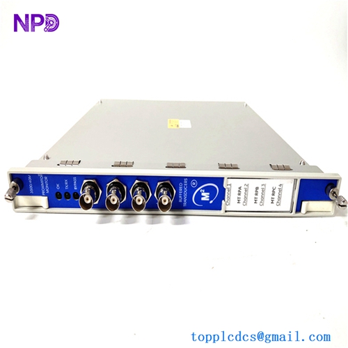
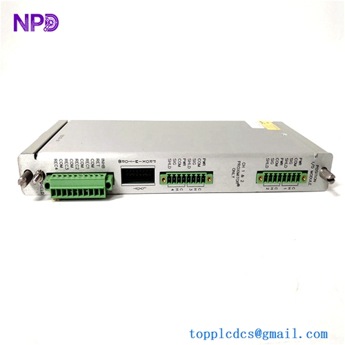
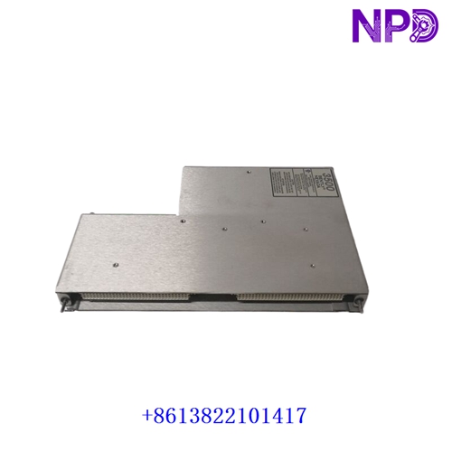
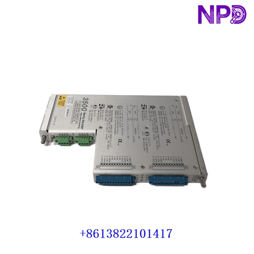
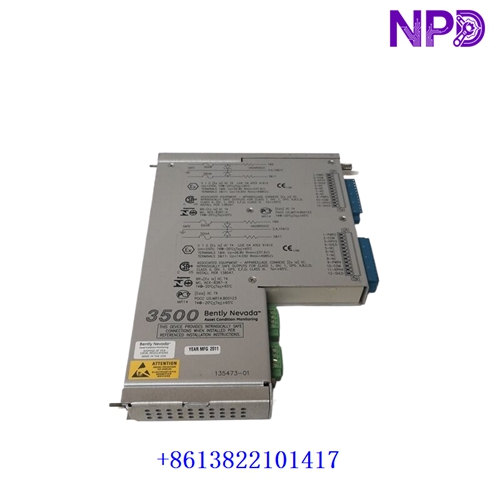
The Bently Nevada 135473-01 is a specialized rear Keyphasor® I/O Module with Internal Barriers and Internal Terminations engineered for the Bently Nevada 3500/25 Enhanced Keyphasor Module assembly within the 3500 Series Machinery Protection System (MPS). Installed in the rear slot of a 3500 rack directly behind the 3500/25 main processing card, the 135473-01 provides field wiring terminals and integrated hazardous-area safety barriers. It conditions incoming raw signals from proximity probes or magnetic pickups to generate precise once-per-turn (or multi-event) timing pulses across the rack backplane.
Key Specifications & Identification
| Attribute | Details |
| Manufacturer | Bently Nevada (a Baker Hughes company) |
| Part Number | 135473-01 |
| System Association | Bently Nevada 3500/25 Enhanced Keyphasor Monitor |
| Module Category | Rear I/O Module with Integrated Intrinsic Safety Barriers |
| Form Factor | Half-height rear card footprint |
| Wiring Interface | Internal screw terminal blocks (direct field wiring) |
| Transducer Compatibility | Proximitor® proximity sensors, magnetic pickups, optical tachometers |
| Hazardous Area Protection | Onboard intrinsic safety barriers for direct hazardous-area transducer wiring |
Primary System Functions
- Phase Reference & Speed Generation: Converts raw probe voltages into digital Keyphasor timing pulses, enabling adjacent 3500 vibration monitors and System 1 software to measure shaft rotation speed and vector parameters (1X, 2X amplitude and phase angle).
- Integrated Intrinsic Safety Barriers: Features factory-integrated zener/galvanic barriers, eliminating the need for external barrier hardware when landing field cables coming from Class I, Div 1 / Zone 0 hazardous environments.
- Signal Conditioning & Isolation: Filters high-frequency electrical noise and isolates transducer signals before passing conditioned timing pulses across the 3500 rack backplane.
- Paired & Redundant Configurations: Supports single, paired (redundant), or multi-channel Keyphasor configurations across half-slot positions to ensure uninterrupted timing signals if a primary sensor fails.
Servicing & Installation Guidelines
- Matching Main Card & I/O Module: Ensure the 135473-01 rear module is paired with a compatible 3500/25 main processing card programmed for internal barrier operation in 3500 Rack Configuration Software.
- ESD Controls: Electrostatic discharge can damage onboard barrier networks and signal conditioning components. Always wear a grounded anti-static wrist strap when installing or removing the card.
- Grounding & Shielding Integrity: Connect field cable shields strictly to the designated SHIELD terminals on the 135473-01 to prevent ground loops while maintaining intrinsic safety insulation standards.
- Sensor Power & Trigger Thresholds: Verify transducer power supplies (-24 V DC for Proximitor sensors) and adjust trigger hysteresis voltage thresholds in software to prevent double-triggering on shaft keyways or notch irregularities.