Description
🔧 Product Overview
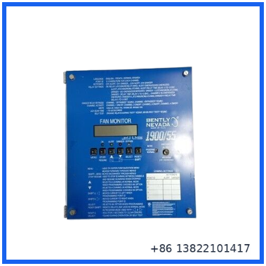
The Bently Nevada 1900/55-01-00-01-01, identified with part number 190201-01, is a Fan Monitor designed for continuous low-frequency vibration monitoring of industrial fans and fan gearboxes.
The monitor provides four independent vibration channels and is particularly suited to machinery operating at relatively low rotational speeds. Bently Nevada documentation specifies the 190501 Velomitor CT transducer for low-frequency applications, with a frequency response of approximately 1.5 to 1000 Hz ±3 dB for fan speeds of 90 RPM or greater.
The 1900/55 can operate as a standalone monitoring device and can also be integrated into a wider machinery condition-monitoring architecture when equipped with the appropriate communication option. Alarm functions, relay behavior, measurement units, display scanning, and other operating parameters can be configured from the front panel.
⚙️ Main Features
🔹 Four independent vibration monitoring channels
🔹 Designed specifically for industrial fan monitoring
🔹 Low-frequency vibration measurement capability
🔹 Suitable for fan gearbox monitoring
🔹 Compatible with Velomitor transducers
🔹 Front-panel configuration
🔹 Programmable alarm relay functions
🔹 Adjustable relay time delays
🔹 Latching or non-latching alarm operation
🔹 Energized or de-energized relay configuration
🔹 Danger relay bypass function
🔹 LCD display for measurement and status information
🔹 Optional communication capability
🔹 Suitable for standalone or integrated machinery monitoring
📋 Product Datasheet
| Parameter | Specification |
|---|---|
| Brand | Bently Nevada |
| Model | 1900/55-01-00-01-01 |
| Part Number | 190201-01 |
| Product Series | 1900 Series |
| Product Name | Fan Monitor |
| Product Type | Vibration Monitoring Module |
| Monitoring Channels | 4 independent vibration channels |
| Primary Application | Industrial fan and fan gearbox monitoring |
| Measurement Type | Low-frequency vibration |
| Recommended Transducer | 190501 Velomitor CT for low-frequency applications |
| Transducer Frequency Response | Approximately 1.5 to 1000 Hz ±3 dB |
| Recommended Fan Speed | 90 RPM or greater |
| Alarm Functions | Alert / Danger monitoring |
| Relay Configuration | Programmable |
| Relay Time Delay | Programmable |
| Relay Behavior | Latching / Non-latching |
| Relay State | Energized / De-energized |
| Danger Relay Bypass | Supported |
| Display | Front-panel LCD |
| Configuration | Front-panel controls |
| Communication | Optional communication card |
| System Integration | Standalone / plant monitoring integration |
| Application | Fan, gearbox and rotating machinery protection |
| Power Supply | Verify exact suffix and hardware revision |
| Dimensions | Verify from actual unit |
| Weight | Verify from actual unit |
| Condition | New Surplus / Used Surplus, depending on the actual unit supplied |
| Country of Origin | Verify from product nameplate |
The four-channel architecture, low-frequency fan monitoring function, front-panel programming, relay options, and optional communication capability are documented for the 1900/55 Fan Monitor.
🌪️ Fan and Gearbox Vibration Monitoring
The 1900/55 was developed for applications where conventional vibration monitoring may not be optimized for the relatively low rotational speeds of large industrial fans.
Typical monitored equipment includes:
- Cooling tower fans
- Industrial ventilation fans
- Forced-draft fans
- Induced-draft fans
- Fan gearboxes
- Process air blowers
- Large rotating fan assemblies
The four channels allow multiple measurement points to be monitored by one unit. This can be useful when vibration needs to be observed at both the fan and gearbox or at several locations around a rotating assembly.
📈 Low-Frequency Vibration Measurement
Low-frequency performance is one of the key characteristics of the 1900/55.
Bently Nevada documentation specifically identifies the 190501 Velomitor CT transducer for low-frequency applications. Its stated response is 1.5 to 1000 Hz ±3 dB, providing suitable measurement coverage for fan systems operating at 90 RPM or higher.
This makes the monitor particularly relevant to large fan systems where imbalance, mechanical looseness, misalignment, or gearbox-related vibration can develop gradually.
🚨 Alarm and Relay Functions
The 1900/55 provides configurable alarm functions for machinery protection.
The front-panel controls allow technicians to configure parameters including:
🔹 Relay time delays
🔹 Alert relay behavior
🔹 Danger relay behavior
🔹 Latching or non-latching operation
🔹 Energized or de-energized relay states
🔹 Danger relay bypass
🔹 LCD scan time
🔹 Measurement units
🔹 Point identification
These settings allow the monitor to be adapted to the operating requirements of individual fan installations.
🖥️ Front-Panel Operation
Unlike systems that require an external engineering computer for every adjustment, the 1900/55 provides front-panel controls for its programmable functions.
Technicians can use the front panel to review measurements, configure alarm behavior, identify measurement points, and adjust other supported operating parameters.
This is particularly useful when the monitor is installed locally in a machinery monitoring cabinet.
🌐 Communication Capability
The 1900/55 can be ordered with a communication card, and the communication capability can also be added later according to the applicable hardware configuration.
With the appropriate communication option, current vibration information can be transmitted to a plant computer or other monitoring system. This information can then be trended to observe changes in vibration over time.
For replacement work, the communication-card configuration should therefore be checked before selecting a spare.
🏭 Typical Applications
The Bently Nevada 1900/55 can be used in:
🔹 Cooling tower fan systems
🔹 Industrial ventilation systems
🔹 Large process fans
🔹 Fan gearbox monitoring
🔹 Power generation plants
🔹 Oil and gas facilities
🔹 Petrochemical plants
🔹 Chemical processing facilities
🔹 Manufacturing plants
🔹 Water treatment facilities
🔹 Continuous-process machinery
🛠️ Installation Notes
Before replacing an existing 1900/55, record the complete configuration of the original monitor.
Recommended checks include:
- Confirm the complete model number and suffix.
- Verify the 190201-01 part number.
- Record all four vibration channel assignments.
- Identify the installed transducer type.
- Verify the transducer wiring.
- Record Alert and Danger setpoints.
- Record relay time-delay settings.
- Check latching/non-latching relay configuration.
- Verify energized/de-energized relay settings.
- Check whether a communication card is installed.
- Verify the power supply configuration.
- Perform a functional vibration-input test after installation.
Do not change alarm parameters during replacement unless the approved machinery protection procedure specifically requires it.
⚠️ Important Replacement Note
The 1900/55 is part of an older Bently Nevada machinery-monitoring platform, so matching the complete configuration is important.
A replacement inspection should compare:
- Full catalog number
- Part number
- Hardware revision
- Number of vibration channels
- Transducer type
- Input wiring
- Alarm settings
- Relay configuration
- Communication-card configuration
- Power supply
- Plant monitoring interface
A visually identical monitor can have a different suffix or option configuration, so the complete identification on the nameplate should be checked before installation.
❓ Common Questions & Answers
Q: What is the Bently Nevada 1900/55?
A: It is a four-channel Fan Monitor designed for low-frequency vibration monitoring on industrial fans and fan gearboxes.
Q: How many vibration channels does it have?
A: The 1900/55 provides four independent vibration channels.
Q: What equipment is it designed to monitor?
A: It is primarily designed for industrial fan systems and fan gearboxes.
Q: Can it monitor low-speed fans?
A: Yes. The system was specifically designed for low-frequency fan vibration monitoring. With the recommended 190501 Velomitor CT transducer, the documented response is approximately 1.5 to 1000 Hz ±3 dB for fan speeds of 90 RPM or greater.
Q: What transducer is recommended for low-frequency applications?
A: Bently Nevada documentation identifies the 190501 Velomitor CT transducer for low-frequency applications.
Q: Can the alarm relays be configured?
A: Yes. Relay time delays, latching/non-latching behavior, energized/de-energized operation, and danger relay bypass can be configured.
Q: Can settings be changed from the front panel?
A: Yes. The monitor’s programmable options can be configured using the front-panel controls.
Q: Does the 1900/55 support communication with a plant computer?
A: Yes, when the appropriate communication card is installed. The communication option can transmit current vibration information for monitoring and trending.
Q: Is the 1900/55 a PLC module?
A: No. It is a dedicated machinery vibration monitoring device rather than a PLC or DCS controller.
Q: What should be checked before replacing one?
A: Verify the complete model number, vibration-channel wiring, transducer type, alarm settings, relay configuration, communication option, and power configuration.
📦 Recommended Bently Nevada Models
- Bently Nevada 1900/55 — Fan Monitor
- Bently Nevada 1900/65A — General Purpose Equipment Monitor
- Bently Nevada 3500/42M — Proximity / Seismic Monitor
- Bently Nevada 3500/45 — Position Monitor
- Bently Nevada 3500/50M — Tachometer Module
- Bently Nevada 3500/60 — Temperature Monitor
- Bently Nevada 3500/22M — Transient Data Interface
- Bently Nevada 3500/92 — Communication Gateway Module
- Bently Nevada 3500/32 — 4-Channel Relay Module
- Bently Nevada 3300/16 — Dual Vibration Monitor
These models cover different machinery-monitoring functions, so compatibility should be determined from the existing monitoring architecture rather than from model similarity alone.
🔍 Inspection Before Shipment
Recommended inspection for a Bently Nevada 1900/55-01-00-01-01 includes:
🔹 Model and part-number verification
🔹 Nameplate inspection
🔹 Front-panel and LCD inspection
🔹 Connector inspection
🔹 PCB and housing inspection
🔹 Power-up test
🔹 Four-channel input verification
🔹 Vibration signal simulation
🔹 Alarm relay testing
🔹 Alert/Danger status verification
🔹 Front-panel control testing
🔹 Communication-card inspection where applicable
🔹 Final visual inspection before packaging
For a maintenance spare, the complete suffix and installed options should be matched before shipment. This is especially important when the existing unit uses the optional communication function.