
Description
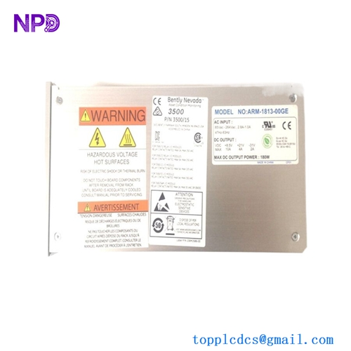
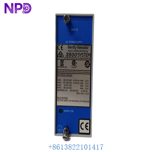
- Model: Bently Nevada 3500/15 (Specific Part Number: 127610-01)
- Brand: Bently Nevada (Baker Hughes / Formerly GE)
- Series: 3500 Machinery Protection System
- Core Function: Converts high-voltage AC source power into regulated DC lines to run internal rack monitor cards
- Product Type: High-Voltage AC Power Supply Module (Legacy Edition)
- Key Specs: 85 to 260 V AC Input Range | 120 W Maximum Output Capacity | Full Rack Subslot Compatibility | Integrated Status Contacts
- Nominal Supply Input: 110 V AC to 220 V AC line ranges
- Absolute Input Voltage Boundaries: 85 V AC to 260 V AC continuous threshold tracking
- Input Line Frequency Window: 47 Hz to 63 Hz standard line matching
- Total Output Rating: 120 W maximum stable DC power delivery capacity across the full internal backplane
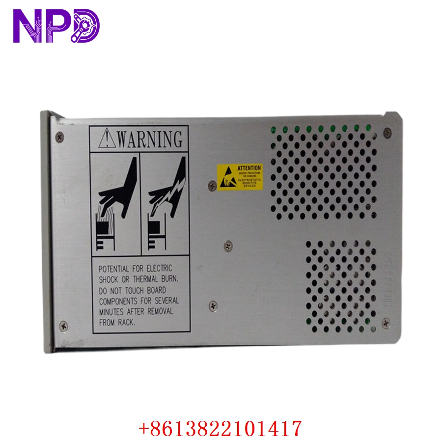
- Physical Footprint Assignment: Full-height module designed to seat exclusively inside the dedicated left-side rack power supply slots
- Redundancy Modes Supported: Dual-supply redundant setup capable (Lower Slot/Upper Slot configuration parity)
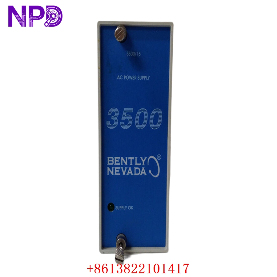
- Onboard Signal Output Contacts: 1x standard Form C relay output for tracking real-time “Supply OK” status conditions
- Galvanic Protection Rating: 1,500 V AC minimum isolation barrier from input line traces down to backplane logic common
- Harmonic Compliance Subsystem: Integrated power factor correction (PFC) circuitry meeting IEC 61000-3-2 standards
BENTLY 3500/15
BENTLY 3500/15

BENTLY 3500/15
BENTLY 3500/15
Application Scenarios & Engineering Pitfalls
The On-Site Reality
Inside critical turbo-machinery protection systems—like a 3,000 RPM steam turbine train or an axial multi-stage process compressor—the Bently Nevada 3500 rack is your primary asset protection layer. The 3500/15 127610-01 module is the foundation that keeps every vibration, thrust, and speed card in that rack powered up. If a power supply fails due to years of heat or a line transient, the system can drop its safety interlocks, potentially causing an emergency machinery shutdown or leaving your critical asset running completely blind. Having a verified, tested replacement ready to drop in is essential to avoid catastrophic, unmanaged machinery failures.
Typical Deployment Scenarios
- Power Generation – Main Steam Turbine-Generator Bearings
Provides continuous power to 3500/42M proximity monitor channels, ensuring zero interruptions in critical shaft vibration and oil film monitoring.
- Oil & Gas – Centrifugal Process Gas Compressors
Powers the crucial thrust position and casing acceleration loops needed to sense surge anomalies before structural asset destruction occurs.
- Chemical Infrastructure – High-Speed Hyper-Compressor Train Protection
Delivers noise-isolated DC rails to key monitoring channels inside high-EMI environments, maintaining clean sensor baselines.
- Water Utilities – Large-Scale High-Pressure Intake Pumps
Ensures continuous monitoring of bearing temperatures and radial vibrations on remote, long-distance water lift systems.
Plant Survival Case Study: Turbo-Compressor Rack Power Restored
- Background: A large petrochemical plant in East China was operating an automated ethylene production loop backed by a critical multi-stage turbo-compressor train. The asset protection layout relied on a standard Bently Nevada 3500 monitor rack configured with a single, non-redundant 3500/15 127610-01 high-voltage AC supply module.
- The Problem: During an exceptionally hot summer week, a localized power factor correction block failed on the plant’s auxiliary substation bus, sending a massive voltage surge straight down the 110 V AC instrument lines. The input filtering stage of the 127610-01 supply module took the brunt of the strike and blew its internal protection circuits, turning the entire vibration monitor rack completely dark. The main DCS lost all machine vibration inputs, meaning the plant was operating blind on a critical asset—a situation that required an immediate process shutdown under local operating safety codes, racking up losses of over $15,000 for every hour of downtime.
- The Solution: The instrumentation engineer reached out to our depot group directly. We bypassed the typical weeks-long factory procurement channels by pulling a clean, verified 127610-01 assembly from our active stock core. The card was installed into our local 3500 rack testing rig, run under full 120 W load configurations for 24 hours to verify zero thermal breakdown, and sent out via a priority air courier within hours.
- The Result: The field maintenance crew received the board early the next morning. They slid the card into the left-side power slot, reconnected the AC terminal plug, and watched the rack successfully complete its self-test loop. The monitoring system returned to full service without needing a full production line shutdown, saving the plant days of costly operational backlogs.
Compatible Replacement Models
When tracking down parts for legacy Bently Nevada power racks, verifying part numbers and checking for the correct matching input modules prevents hardware mismatch errors on-site.
| Original Part Number | Alternative Model | Compatibility Level | Key Differences / Structural Variances | Required On-Site Modification Steps | Cost Variance |
| 3500/15 127610-01 | 3500/15 141758-01 | ✅ Drop-in Replacement | Next-generation universal AC power supply module. Slightly improved efficiency over the older 127610 series. | Direct mechanical swap. Uses the exact same chassis rails and backplane connections. No re-wiring required. | +20% |
| 3500/15 127610-01 | 3500/15 127610-02 | ⚠️ Software Compatible | Low-Voltage AC configuration variant designed to operate on 24 V AC line paths instead of high-voltage lines. | Requires a different source power supply line. You must verify that your input voltage matches the low-voltage limits before installation. | Equivalent |
| 3500/15 127610-01 | 3500/15 127620-01 | ❌ Hardware Incompatible | High-Voltage DC configuration module family designed to run on plant station battery banks. | Internal input components and filtering paths are completely different. Do not connect to AC lines. | +15% |
Quality Assurance & Testing Standard Operating Procedure
To address the high-reliability needs of critical machinery protection systems, every single Bently Nevada power supply is run through a documented, multi-step technical evaluation before being cleared for shipment.
[Inbound Serialization Log] ➔ [Optical Thermal & Capacitor Audit] ➔ [Galvanic Isolation Safety Test] ➔ [24-Hour 120W Full-Rack Load Soak] ➔ [ESD Secure Packing] 1. Inbound Serialization & Visual Evaluation
- Authenticity Profiling: Verifying the physical manufacturer nameplate, internal board traces, and manufacturing revision codes against Bently Nevada production history.
- Chassis Assessment: Detailed review of the aluminum faceplate, chassis alignment rails, and backplane interface connector pins to ensure zero bending or structural damage.
2. Optical Thermal & Capacitor Life Inspection
- Solder Joint Review: Microscopic tracking of all surface-mount and high-power connections to check for micro-fracturing from prolonged exposure to cabinet vibration.
- Capacitor Lifecycle Audit: Detailed review of the heavy internal storage and smoothing capacitors to ensure zero evidence of component swelling, drying out, or internal electrolyte leakage.
3. Galvanic Isolation Safety Verification
- Insulation Resistance Execution: Using a specialized insulation tester to apply 500 V DC between the primary AC input terminals and the low-voltage logic ground plane tracks.
- Acceptance Threshold: The insulation barrier must measure above 10 MΩ to ensure complete protection against field spikes bridging into the rack’s primary backplane logic.
4. 24-Hour 120W Full-Rack Load Soak
- The Testing Environment: The 3500/15 127610-01 module is installed into a live 3500 chassis test rig equipped with electronic load-emulation cards mimicking a fully populated rack.
- Dynamic Load Run: The power supply is run continuously for over 24 hours at its maximum rated output limits. We monitor the stability of the internal DC voltage rails and record surface temperature variations to guarantee zero thermal component drift.
- Status Contact Test: Verifying the clean operation of the onboard “Supply OK” relay paths during active power-up, run, and unpowered cycles.
5. Final Quality Sign-Off and Secure ESD Packaging
- Tagging Protocol: The testing technician signs and applies a serialized “QC Passed” sticker directly onto the anti-static packaging layer.
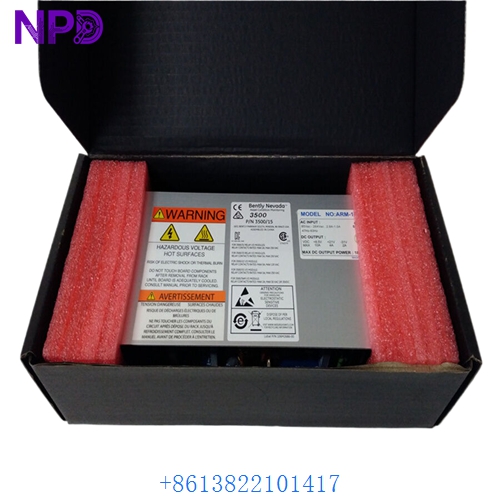
- ESD Shielding: The module is sealed inside an industrial-grade anti-static, moisture-barrier bag filled with fresh desiccant packs.
- Mechanical Protection: Securely housed inside custom shock-absorbing foam layers within a heavy shipping box to eliminate any transportation risks.
High-Availability Power Rack Troubleshooting Quick Reference
❗ SAFETY FIRST: Disconnect and lock out the external AC power feed lines before loosening the power input connector plug or handling the rear terminal paths. High voltages are present on the input connector block when the supply line is energized.
Q: The rack remains completely unpowered, and the front panel green “Supply OK” LED on the 3500/15 card is dead, but adjacent field instruments show active power.
A: Correlation: High. This behavior indicates that the internal input protection fuse or the main switching transistor block on the 127610-01 module has blown due to an external surge or over-temperature condition.
- Safely isolate the power feed line.
- Unplug the AC terminal block from the rear input module. Use a digital multimeter to verify that input voltage measures within the 85 to 260 V AC threshold right at the cable end.
- If input power is present but the module front panel shows zero activity, the internal power stage is compromised. Slide the module out and swap it for a verified spare.
Q: The rack operates normally most of the time, but the DCS intermittently logs a “Rack Power Supply Fault” alarm while the individual monitor cards stay active.
A: Correlation: High. This pattern indicates that the internal monitoring circuit or the physical “Supply OK” relay contact tracking paths on the 3500/15 card are starting to fail, or the rack’s dual-redundant power supplies are exhibiting voltage balance drift.
- Connect a digital multimeter across the “Supply OK” terminal screw connections on the rear of the rack.
- Check for an intermittent open circuit on the dry contact lines while gently tapping the front panel.
- If you are running a dual-redundant supply setup, pull the suspect module and verify its output stability on a test fixture to ensure it isn’t dropping out under transient thermal loads.
Q: In a dual-redundant power supply setup, the lower module shows a steady “Supply OK” LED, but the upper module displays a flashing red “Fault” indicator.
A: Correlation: High (Internal hardware failure). A flashing or steady red fault indicator on a redundant 3500/15 card means its internal tracking diagnostic loop has sensed an output voltage level that falls outside the safe operating window for the backplane.
- Connect your 3500 Rack Configuration software through the rack’s communication gateway module.
- Open the diagnostic event log buffer to review the power supply fault registers.
- Honest technical truth: Do not leave the system running on a single supply long-term. Your fallback redundancy is gone. Prepare your spare board, verify the input voltage rails, and slide out the faulty upper unit to complete a hot-swap replacement.
❗ Critical Installation Guidelines for On-Site Technicians
- Redundant Pair Voltage Matching: If you are installing this board into a dual-redundant supply configuration rack, ensure that both modules match in their input classification (e.g., combining two high-voltage AC cards together). Never mix a high-voltage AC supply card with a low-voltage DC supply module in the same active pair slot layout. This will cause severe backplane current mismatches and trigger system faults.
- Secure the Rear Input Module (RIM): The 3500/15 system splits its architecture between the front-slide power card and the rear-mounted input module. Ensure that the fastening screws on both the front module and the rear terminal connector block are turned down completely. Loose connections can lead to intermittent arc faults, causing unexpected monitor rack reboots.
- Verify “Supply OK” Relay Loop Wiring: When terminating the status contact lines back to your plant’s central DCS cabinet, ensure the loop is wired into a supervised digital input path. This configuration ensures that if the field wiring line breaks or a terminal block comes loose, the system will immediately flag a connection fault rather than silently losing its power supply warning link.