Description
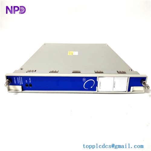
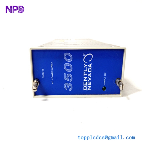
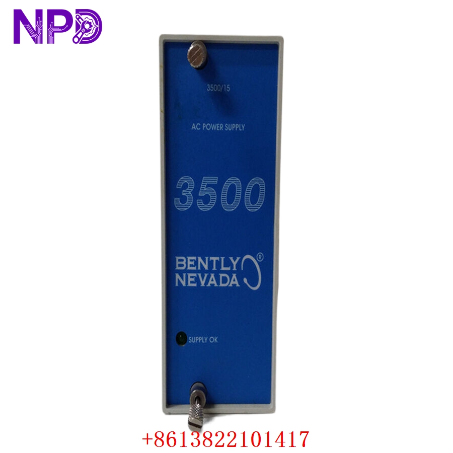
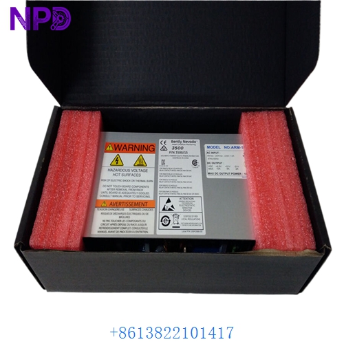
- Model: Bently Nevada 3500/15 (Common PNs: 127610-01, 106M1079-01, 125840-01)
- Brand: Bently Nevada / Baker Hughes (USA)
- Series: 3500 Machinery Protection System
- Core Function: Supplies regulated, redundant operating power to all modules in a 3500 rack, Original New Surplus condition
- Type: Rack Power Supply Module
- Key Specs: Supports High-Voltage AC/DC or Low-Voltage DC | Redundancy Capable | Installs in Left-Side Dedicated Slots
- Input Voltage Options (High-Voltage AC): 175 V to 264 V AC RMS, 47 Hz to 63 Hz
- Input Voltage Options (Low-Voltage AC): 85 V to 132 V AC RMS, 47 Hz to 63 Hz
- Input Voltage Options (High-Voltage DC): 120 V to 373 V DC
- Input Voltage Options (Low-Voltage DC): 20 V to 30 V DC
- Full-Rack Power Capacity: Up to 100 W total output matching a fully populated 3500 rack
- Output Isolation Voltage: 3,000 V AC RMS input-to-output structural barrier
- Efficiency Rating: 75% typical at full rated load conditions
- Hold-Up Capacity: Minimum 20 ms survival time during input line drops at 120 VAC
- Operating Temperature Limits: -30 °C to +65 °C (Standard internal industrial chassis ambient)
- Status Relay Rating: 5 A at 24 V DC / 120 V AC SPDT contact configuration
- Physical Footprint: Standard half-rack width, takes up dedicated power slots
BENTLY 3500/15
BENTLY 3500/15
BENTLY 3500/15
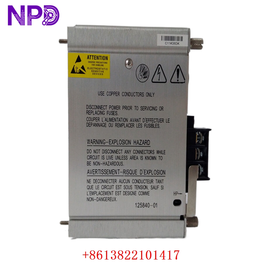
BENTLY 125840-01 3500/15
BENTLY 3500/15
Part 4: Installation & Configuration Guide
Phase 1: Pre-Installation (Estimated Time: 15 minutes)
⚠️ Safety First:
- Coordinate with operations to confirm that the critical machinery being monitored (e.g., turbine, compressor) is either offline or that its safety trip loops are bypassed at the DCS/PLC level.
- If you are replacing a non-redundant supply, the entire 3500 rack will go dark. Ensure this will not trigger an automatic interlock shutdown.
- Turn off the external circuit breaker providing supply lines to the specific power supply slot you are working on.
- Apply standard Lockout/Tagout (LOTO) padlocks and tags to the supply source breaker.
Tool Preparation:
- Static-dissipative wrist strap and an ESD-safe workspace mat
- Standard slotted screwdriver for terminal blocks
- No. 2 Phillips screwdriver for faceplate screws
- Fluke 115 Digital Multimeter
- Marker tags and a smartphone camera
Backup Procedures:
- Connect a laptop running 3500 Rack Configuration Software to the rack’s transient data interface or monitor card. Save a full export of the rack profile and event history logs before doing any physical work.
- Take clear photos of the rear-facing power input terminal blocks, noting exactly how the Line, Neutral, Ground, and Status Relay alarm lines are wired.
Phase 2: Removal (Estimated Time: 10 minutes)
Steps:
- Verify with your multimeter that the incoming supply cables at the rear of the rack read 0 V (both AC and DC checks).
- Unfasten the screw terminals on the rear power input module (PIM) and slide the power wires out. Wrap tape over the bare wire ends to keep them isolated.
- Disconnect the status relay alarm connector from the rear of the PIM.
- Move to the front of the 3500 rack and locate the 3500/15 power supply module in its dedicated left-hand slot.
- Loosen the two captive Phillips screws on the upper and lower edges of the front faceplate.
- Pull the injector/ejector handles outward firmly to back the module out of its backplane connection pins. Slide the card smoothly out of the chassis tracks.
⚠️ Key Notes:
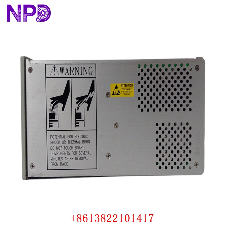
- The 3500/15 power supply card consists of a front-loading power supply module and a rear-mounting Power Input Module (PIM). When replacing a power supply due to an internal component fault, ensure you check whether the issue lies in the front regulation board or the rear filter assembly.
Phase 3: Installation (Estimated Time: 15 minutes)
Steps:
- ESD Protection: Strap on your anti-static wrist guard before opening the sealed antistatic wrap containing the new surplus 3500/15 module.
- Voltage Jumper Verification: Look closely at the side configuration jumpers or the part number matrix on the unit. Ensure the new module matches the input feed voltage of your facility (e.g., confirming a High-Voltage AC board is not being paired with a 24V DC field input).
- Module Seating: Slide the new module card into the dedicated guide tracks on the left side of the front rack space. Push it inward firmly until the backplane connectors seat completely.
- Fasten Faceplate: Fold the ejector handles inward and tighten down the two captive faceplate screws until the module sits flush with the adjacent slots.
- PIM Setup and Wiring: If you are replacing the rear PIM as well, mount it to the back slot rails. Wire the ground conductor first, followed by the Line and Neutral power lines exactly like your reference photos. Re-insert the status relay alarm terminal block.
Self-Check Checklist:
- [ ] Input voltage configuration of the new supply matches the field utility power supply exactly
- [ ] Rear grounding stud is secured directly to the main instrument ground bar
- [ ] Front panel thumbscrews are hand-tightened down completely with no gaps
- [ ] All loose tools, stray hardware, and wire clippings are cleared from the rack tracks
Phase 4: Power-On & Testing (Estimated Time: 20 minutes)
Pre-Power Checks:
- Use your multimeter to verify that the resistance between the power input terminals and the rack frame is high (no short circuits). Ensure that the line voltage at the breaker output falls within standard operating tolerances.
Power-On Steps:
- Remove LOTO locks and flip the external input power breaker back to ON.
- Observe the Front LEDs: The green SUPPLY OK light on the new 3500/15 faceplate should light up instantly. If the red FAIL LED illuminates or the green light blinks, cut power immediately.
- Redundancy Validation (If Applicable): If your rack uses dual redundant power supplies, flip the breaker for Supply A off and verify that Supply B automatically picks up the full load without causing any blinks or reset faults on the monitoring cards. Repeat the test for the other supply.
- Launch your 3500 Configuration Software utility. Check the System Event Log to verify that the rack acknowledges the new power supply module and that no power-rail diagnostic faults are present.
- Re-engage any bypassed DCS protection trip relays once the rack stabilizes for 15 minutes without any active system alarms.
- Record the new module’s serial number and modification tracking state inside the machinery history ledger.
Part 5: Customer Cases & Industry Applications
Case 1: Redundant Power Supply Failure at a Gas Pipeline Compressor Station
Situation: A gas pipeline compressor facility in Western Canada relies on a Bently Nevada 3500 rack system to monitor vibration across an essential gas turbine drivetrain. The system was configured with dual redundant 3500/15 power supplies. During an electrical storm, a severe line surge damaged the primary supply module (Supply A), leaving the rack running entirely on Supply B.
Task: The system event logs triggered a critical alarm in the control room showing “Power Supply A Fault.” Since the rack was no longer redundant, any secondary glitch or drop on Supply B would shut down the entire vibration monitoring system, triggering an automatic safety trip that would stop the gas pipeline pump and cost the operator considerable revenue.
Action: The plant engineer reached out to our depot to source a replacement module before Supply B experienced any issues. We processed an original new surplus 3500/15 high-voltage AC card from our warehouse. We verified its power rails on our internal 3500 rack test bed and shipped the part via priority overnight air express.
Result:
- Uptime Maintained: The replacement module reached the remote station within 24 hours. Because the 3500/15 supports hot-swapping in redundant setups, the maintenance technician slid the new card directly into Slot A without powering down the rack or interrupting the live turbine monitoring circuits.
- Risk Mitigated: Full system redundancy was restored in under 10 minutes, protecting the line from an unexpected multi-day shutdown.
- Customer Voice: “Being able to get an original, un-used 3500/15 supply on short notice saved us a lot of stress. It slid right in, hot-swapped perfectly, and cleared the system alarm instantly.”
Case 2: Upgrading a Legacy Rack Setup during a Refinery Turnaround
Situation: A refinery in Texas planned a major scheduled turnaround to overhaul its main catalytic cracking unit. The plant’s primary machinery protection system utilized a first-generation Bently Nevada 3500 monitor array running a single, non-redundant 3500/15 power module that had been in continuous service for over a decade.
Task: During maintenance planning, the reliability team flagged the single power supply as a potential single point of failure for the entire refinery loop. They decided to upgrade the rack to a redundant power supply layout during the shutdown window. However, local distributors quoted a 6 to 8-week lead time for new production modules, which would miss the turnaround schedule completely.
Action: The procurement team reached out to us to locate matching components from our un-used surplus holdings. We provided a matching pair of 106M1079-01 high-efficiency power supplies along with their corresponding rear input modules, ensuring both cards belonged to the same production batch to maintain balanced load-sharing.
Result:
- Turnaround Schedule Saved: The parts arrived at the site two days before the maintenance window opened. The turnaround crew easily upgraded the rack to a dual-redundant power setup.
- Long-Term Protection: This upgrade extended the useful lifespan of the legacy monitoring infrastructure by years, saving the facility from an expensive full-system replacement while significantly boosting system reliability.
Part 6: Frequently Asked Questions (FAQ)
Q1: Can I hot-swap a 3500/15 power supply module while the machinery monitoring rack is live?
A: Yes, but only if your 3500 rack is explicitly configured with dual redundant power supplies and both Supply OK LEDs were active before the failure. In a redundant setup, you can safely extract the failed power module from the front slots without shutting down the rack.
However, if your rack only has a single power supply module, removing it will cut power to the backplane instantly, turning off all monitoring cards and potentially triggering automated machinery trip loops in your connected DCS.
Q2: Why are there different part numbers like 127610-01 and 106M1079-01 for the 3500/15?
A: These variations represent different manufacturing generations and engineering updates introduced by Bently Nevada over the lifecycle of the 3500 series. Part number 127610-01 refers to the standard legacy high-voltage AC/DC power supply module.
The newer part number 106M1079-01 is a high-efficiency replacement module designed to run cooler and provide more reliable power distribution across fully loaded racks. Both versions are fully slot-compatible, but it is best practice to use identical part numbers if you are running a redundant side-by-side setup.
Q3: How do I know if my 3500/15 is configured for High-Voltage AC or Low-Voltage DC?
A: You can easily verify the input power requirements by checking the product option stickers on the front faceplate or looking at the layout of the rear Power Input Module (PIM).
High-Voltage AC modules are built to handle standard facility power lines (115 V to 230 V AC), while Low-Voltage DC modules are designed to run on 24 V DC plant battery banks. Never plug a low-voltage module into a high-voltage line, as this will instantly destroy the internal voltage regulators.
Q4: What is the purpose of the Status Relay terminal block on the rear PIM?
A: The status relay is a built-in safety feature that provides a hardwired alarm connection to your plant’s central control room or DCS.
Under normal conditions when the power supply is healthy, the relay remains energized. If the 3500/15 loses input power, experiences an internal component failure, or its output voltage drops below safe limits, the relay de-energizes instantly. This triggers an immediate alert for the operations team, even if the rack’s digital communication links go offline.
Q5: How do your New Surplus Bently Nevada modules compare to cheaper refurbished alternatives?
A: Refurbished 3500/15 modules are typically salvaged from older, decommissioned plants. Third-party repair shops usually just replace the blown input fuses or worn-out cooling fans, leaving the old power transistors and transformer coils in place. These old components are prone to failing unexpectedly when subjected to thermal stress in a live rack.