
Description
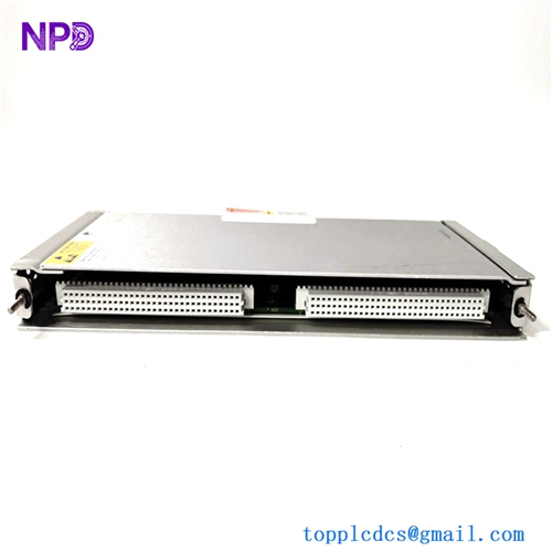
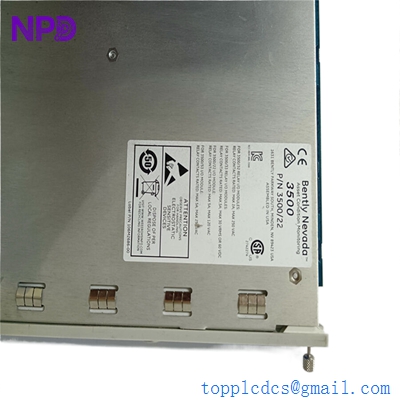
- Model: Bently Nevada 3500/22M (Specific Part Number: 288055-01)
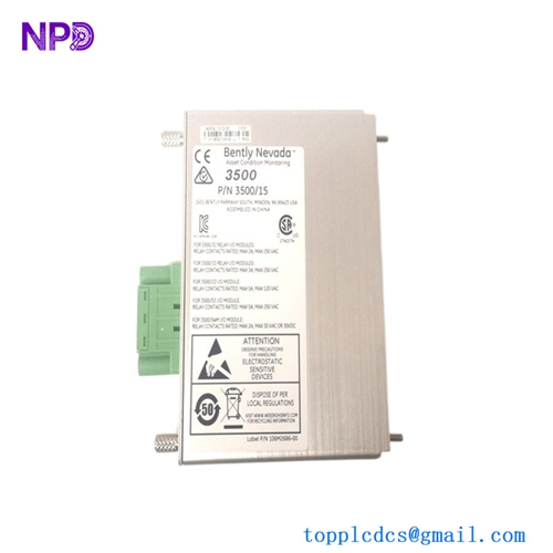
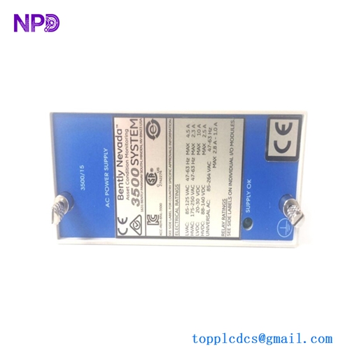
- Brand: Bently Nevada / Baker Hughes (USA)
- Series: 3500 Machinery Protection System
- Core Function: Interfaces the 3500 rack with configuration software and diagnostic platforms (System 1) to stream static and dynamic transient data, Original New Surplus condition
- Type: Transient Data Interface (TDI) Module (Standard Version)
- Key Specs: Ethernet & USB Connectivity | Support for System 1 Diagnostic Software | Slot Placement next to Power Supplies
- Processor Architecture: High-speed digital signal processing subsystem for steady-state and transient waveforms
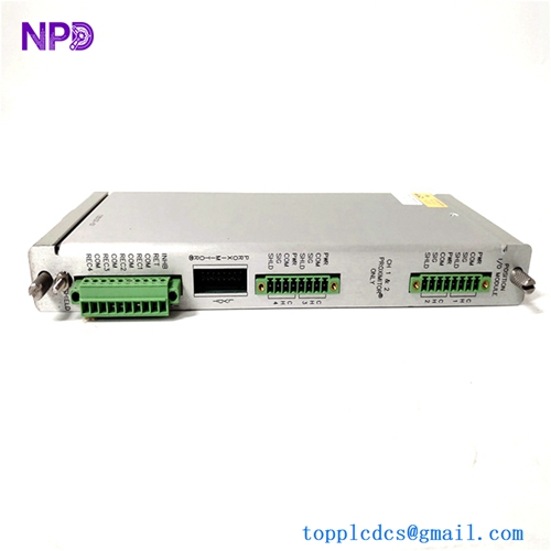
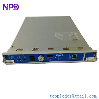
- Communications Interfaces:
- Front Panel: Type-B USB port (for local rack configuration)
- Rear Panel (on I/O module): 10/100 Base-T RJ45 Ethernet port & TDM connection
- Supported Protocols: Modbus TCP/IP, Bently Nevada proprietary encapsulation, SMTP
- Dynamic Data Collection: Simultaneous collection of continuous waveform data across all channels for spectral analysis, orbit plots, and time-synchronous trends
- Transient Captures: Automatic triggering based on speed changes (Startup/Shutdown events) or parameter alarms (Trip data catching)
- Data Buffer: Onboard non-volatile flash memory to prevent data gaps during network dropouts
- Operating Temperature Limits: -30 °C to +65 °C
- Physical Constraints: Fits into the dedicated slot directly to the right of the rack power supply modules (Slot 1)
BENTLY 3500/22M 288055-01
BENTLY 3500/22M 288055-01
BENTLY 3500/22M 288055-01
Part 4: Installation & Configuration Guide
Phase 1: Pre-Installation (Estimated Time: 15 minutes)
⚠️ Safety First:
- Coordinate with operations to confirm that the critical rotating machinery monitored by this rack is either offline or that its automatic protection trip loops are temporarily bypassed in the plant DCS or PLC system.
- Although the 3500/22M TDI does not directly execute channel trip logic, it acts as the primary communications hub for the rack. Removing it while active will disrupt data streaming to System 1 and may trigger a rack communication failure alarm on the DCS control desk.
- Switch off power feeds to any external networking switches or serial links connected to this specific interface node.
- Apply standard Lockout/Tagout (LOTO) procedures on auxiliary communication cabinet power distribution units if required.
Tool Preparation:
- Static-dissipative wrist grounding strap and an ESD-safe workspace mat
- No. 2 Phillips screwdriver for faceplate screws
- Slotted precision screwdriver for I/O module clamps
- Laptop with 3500 Rack Configuration Software and a standard USB A-to-B cable
- Fluke 115 Digital Multimeter
- Marker tags and a mobile phone camera
Backup Procedures:
- CRITICAL: Connect your configuration laptop to the existing TDI’s front USB port. Launch the 3500 Configuration Software, select “Connect to Rack,” and perform a complete download/export of the current
.w35rack configuration file. Save this to your master engineering directory. Without this file, you will have to manually reprogram every monitor slot in the rack.
Phase 2: Removal (Estimated Time: 10 minutes)
Steps:
- Move to the rear of the 3500 rack and unplug the Ethernet network cable from the TDI I/O module port.
- If the serial Modbus or TDM ports are wired, label the wires clearly, take a reference photo, and remove the terminal blocks.
- Return to the front of the rack. Locate the 3500/22M 288055-01 module positioned in the slot next to the power supplies.
- Loosen the upper and lower captive Phillips screws anchoring the front faceplate to the rack frame.
- Pull the upper and lower injector/ejector tabs outward simultaneously to unseat the module from its backplane socket pins.
- Slide the circuit card smoothly out of the guide tracks and immediately place it inside an ESD-shielded storage bag.
⚠️ Key Notes:
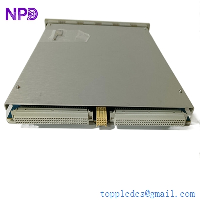
- The 3500/22M system uses a paired configuration: the front-loading TDI main module (288055-01) and a matching rear I/O module. If you are upgrading from an older 3500/20 RIM module, you must replace both the front and rear boards at the same time to ensure correct operation.
Phase 3: Installation (Estimated Time: 15 minutes)
Steps:
- ESD Protection: Secure your anti-static wrist strap before opening the sealed factory packaging containing the new surplus 288055-01 card.
- Hardware Revision Check: Verify the part number on the board sticker reads 288055-01, confirming it is the correct standard TDI module.
- Card Seating: Slide the card carefully into the dedicated guide tracks of Slot 1 from the front of the rack. Push the module firmly inward until you feel the backplane pins lock into the card sockets.
- Mechanical Lock: Fold the extraction handles inward and tighten the top and bottom captive Phillips screws down until the faceplate is flush with the rack layout.
- Rear Network Restore: Move to the rear of the chassis and ensure the matching TDI I/O board is seated properly. Re-plug the Ethernet network cable and any auxiliary terminal blocks based on your reference photos.
Self-Check Checklist:
- [ ] Master rack configuration file (
.w35) is saved and accessible on the maintenance laptop - [ ] Front panel thumbscrews are fully tightened with no loose alignment play
- [ ] Network RJ45 connector clicks securely into the rear I/O port
- [ ] Work areas are clear of stray hardware and tool components
Phase 4: Power-On & Configuration Loading (Estimated Time: 25 minutes)
Pre-Power Checks:
- Verify that the rack power supplies are stable and that the local network switch is active before attempting to initialize communication with the new TDI.
Configuration Loading Steps:
- With the rack powered on, look at the front panel of the new TDI module. The OK LED will flash erratically or remain off, and the CONFIG FAULT LED may light up. This is normal because the new surplus module does not contain your plant’s custom configuration data yet.
- Connect your maintenance laptop to the front USB port of the 288055-01 card using your USB cable.
- Open the 3500 Rack Configuration Software. Open your saved
.w35profile file. - Select “Communication Code / Connect Options” and select USB Connection.
- Click Upload Configuration to Rack. Enter any required security passwords. The software will push the configuration to the TDI, which will distribute the parameters to every monitor card across the backplane.
- Verify System LEDs: Once the download completes, the TDI will reboot itself. The green OK LED should turn solid, the blue TM (Trip Multiply) LED should mirror your system status, and the red FAIL or CONFIG FAULT lights must turn off completely.
- Open System 1 diagnostic software to verify that steady-state trends and dynamic waveform data are streaming properly across the Ethernet network link.
- Re-engage any bypassed interlock circuits at the DCS panel once the rack logs display clear of system faults for 15 minutes. Record the new serial number in your site ledger.
Part 5: Customer Cases & Industry Applications
Case 1: Restoring Diagnostics for a Critical Steam Turbine Group
Situation: A large combined-cycle power plant in Western Europe relies on Bently Nevada 3500 protection racks to monitor a high-output steam turbine generator. During a routine IT infrastructure update, a network voltage spike fried the main communications processor on the rack’s primary interface card, part number 288055-01, causing System 1 diagnostic software to lose all real-time waveform tracking.
Task: While the local monitor cards continued to execute basic vibration trip protection, the engineering team was left completely blind without access to high-resolution orbit plots and spectral trend data. With an upcoming seasonal grid load ramp scheduled, management refused to run the turbine without full System 1 diagnostic visibility, meaning any prolonged delay in sourcing a replacement card would halt operations.
Action: The plant’s instrumentation team contacted our support line. We verified an un-used surplus 3500/22M 288055-01 card in our inventory. Our lab staff initialized the board on our test chassis, updated it to the proper base firmware revision, and verified both the front USB port and rear Ethernet data pipelines. The module was packed securely and shipped via priority overnight express.
Result:
- System Restored: The replacement TDI reached the plant within 14 hours. The maintenance engineer connected via the front USB port and restored the site configuration file in under 15 minutes.
- Full Visibility: Real-time waveform streaming to System 1 resumed instantly, giving engineers the data tracking they needed to safely proceed with the seasonal load ramp.
- Customer Voice: “Losing our diagnostic data stream right before a major grid run was critical. Sourcing a clean, verified 288055-01 board from your stock saved us days of troubleshooting and kept our production timeline on schedule.”
Case 2: Upgrading a Petrochemical Compressor Protection Matrix
Situation: A petrochemical refining asset was running a high-speed centrifugal compressor using a legacy Bently Nevada 3500 system equipped with an older 3500/20 Rack Interface Module (RIM). The legacy RIM could only stream static variables via basic serial links, leaving the plant unable to perform advanced predictive maintenance or log transient startup data.
Task: During a planned turnaround window, the reliability team decided to upgrade the communication layer to a 3500/22M TDI setup to integrate the rack with modern System 1 optimization software. However, the OEM quoted a lengthy factory lead time that exceeded the plant’s turnaround schedule.
Action: The procurement manager contacted us to secure the necessary components from our un-used surplus inventory. We supplied a brand-new surplus 288055-01 TDI module in its original sealed anti-static packaging, allowing the facility to execute the hardware upgrade without delaying their maintenance window.
Result:
- Successful Integration: The plant engineers swapped out the old hardware and configured the new TDI module during the scheduled shutdown window.
- Predictive Maintenance Capability: The compressor system can now capture high-resolution transient data during machine startups and shutdowns, allowing the engineering team to identify minor mechanical anomalies before they lead to unexpected equipment breakdowns.
Part 6: Frequently Asked Questions (FAQ)
Q1: What is the primary operational difference between the older 3500/20 RIM and the 3500/22M TDI?
A: The older 3500/20 Rack Interface Module (RIM) was designed primarily to handle basic rack configuration data and low-density static values over slow serial links.
The 3500/22M Transient Data Interface (TDI) features a significantly more powerful digital signal processor capable of streaming both static parameters and high-resolution, dynamic transient data waveforms (such as continuous orbit plots and spectrum trends) directly to System 1 diagnostic software over fast Ethernet networks.
Q2: Why is the CONFIG FAULT LED illuminated on my new 288055-01 module right after installation?
A: A lit CONFIG FAULT LED is completely normal for a newly installed surplus module. This indicator simply means that the replacement TDI’s memory blank does not yet match the specific hardware arrangement of the adjacent monitor cards in your rack.
Once you connect your laptop to the front USB port and upload your site’s saved .w35 configuration file using the 3500 Rack Configuration Software, the module will ingest the correct profile and clear the fault light automatically.
Q3: Can I swap out the 288055-01 TDI module while the machinery protection rack is powered up and live?
A: Mechanically, the 3500/22M card supports hot-swapping under specific conditions, but it is highly recommended to bypass all machinery trip loops before pulling the module.
While removing the TDI will not stop the individual monitor cards from executing local safety trips, the sudden break in backplane communications can generate error logs or transient network anomalies that could be misinterpreted by connected DCS interlock systems. Always secure your safety loops first.
Q4: Why select a New Surplus 3500/22M module over a cheaper refurbished alternative found online?
A: Refurbished 3500/22M modules are typically salvaged from decommissioned industrial plants or older control panels. Third-party repair shops often clean the outer casing and test basic connectivity, but they leave aged internal memory chips, processing chips, and capacitors intact. These old components are prone to failing unexpectedly when subjected to continuous data streaming.
Our New Surplus units are authentic, un-used components stored in climate-controlled warehouses. They provide factory-original component lifespans and come backed by a full 12-month warranty, providing reliable data streaming for your machinery protection system without the risks of refurbished hardware.
Q5: How do you verify the data transmission integrity of the TDI before shipping?
A: Every 288055-01 TDI module undergoes rigorous testing on our specialized Bently Nevada 3500 test beds before leaving our facility. We connect the unit to a live rack configuration, hook up a multi-channel signal generator, and simulate dynamic machine vibration waveforms.