Description
Product Core Brief
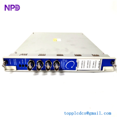
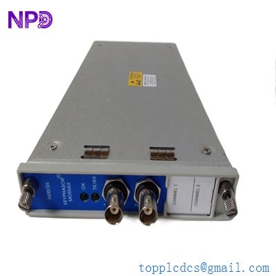
- Model: BENTLY 3500/25
- Brand: Bently Nevada (Baker Hughes)
- Series: 3500 Machinery Protection System
- Core Function: Provides buffered Keyphasor timing signals for vibration analysis
- Type: Enhanced Keyphasor Module (half-height)
- Key Specs: Dual-channel Keyphasor inputs Buffered outputs Rack-mounted in 3500 system
BENTLY 3500/25
Technical Specifications
- Module Type: Enhanced Keyphasor® Module (3500/25)
- Channels: 2 independent Keyphasor channels
- Input Signal Type: Proximity probes or magnetic pickups
- Input Signal Range: +0.8 V to −21.0 V (non-isolated) or +5 V to −11 V (isolated)
- Speed/Frequency Input Range: 1 to 1,200,000 CPM (0.017 Hz to 20 kHz)
- Output: Buffered digital Keyphasor pulses via front/rear connectors
- Transducer Power: –24 V DC, 40 mA per channel
- Power Consumption: ~3.2 W typical
- Operating Temperature: −30°C to +65°C (varies with I/O termination)
- Mounting: Half-height slot in Bently 3500 rack
- Compatibility: Downward compatible with legacy 3500 Keyphasor modules
-
Installation & Configuration Guide
Total time: ~30 minutes (experienced technician)
Stage 1: Pre-Installation
⚠️ Ensure power is isolated: Lock out the 3500 rack and verify zero volts with a multimeter (e.g., Fluke 87V).
- Label existing keyphasor cables carefully before removal.
- Photograph current connections and 3500 rack slot positions.
Tools needed: ESD strap, multimeter, small flat screwdriver, labels.
Stage 2: Remove Old Module
- With rack de-energized, release module latch and remove the 3500/25 from its half-height slot.
- Gently disconnect front and rear connectors.
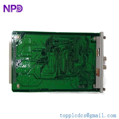
- Inspect backplane and card edges for burn marks or loose pins — these are common reliability culprits if vibration data looked noisy.
Stage 3: Install New 3500/25
- Clip ESD strap and unpack the new module.
- Slide module into the designated half-height slot, ensuring the backplane edge connectors seat fully.
- Reconnect any Keyphasor I/O termination blocks (rear modules).
- Confirm cable terminations: shield to ground at one point, no multiple grounds.
Checklist before power:
- Correct slot and orientation
- Secure connectors
- Cable routing avoids sharp bends (<50 mm radius)
Stage 4: Power-On & Test
- Re-energize only the 3500 rack (not field power).
- Confirm LEDs (OK, TX/RX) indicate healthy backplane communication.
- Use monitoring software (e.g., 3500/46 configuration tool) to verify Keyphasor inputs.
- Validate a running machine’s once-per-turn signal for clean edges (no chatter).
Typical issues:
- No Keyphasor edges → check pickup/proximitor wiring first.
- Erratic signals → poor grounding or threshold settings.
BENTLY 3500/25
Customer Cases & Industry Applications
Case 1: Gas Turbine 1X Phase Reference Failure
Situation:
A 3500 rack in a gas turbine protection system began reporting missing phase references, compromising 1X vibration data.Task:
Available local stock included a 3500/25 module. A new module was sourced immediately.Action:
Module was tested in our shop for continuity and output buffering performance before dispatch. Replacement onsite restored phase references and vibration vector analysis.Result:
Downtime reduced by more than 12 hours, and maintenance updated stock levels to include one 3500/25 plus one spare Keyphasor I/O block.Case 2: Compressor Station Redundancy Rollout
Situation:
A compressor station operating two identical trains wanted to add redundancy to critical Keyphasor inputs.Task:
Install two 3500/25 modules in parallel (TMR configuration) so primary and secondary timing signals feed multiple monitor modules.Action:
Modules configured in adjacent half-height slots with proper cable terminations and threshold settings.Result:
Operators gained confidence in phase-locked vibration data, crucial for advanced diagnostics and early fault detection.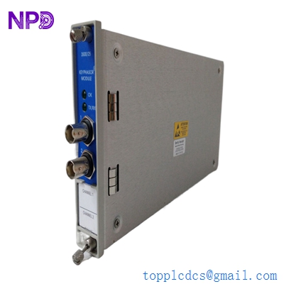
BENTLY 3500/25
Frequently Asked Questions (FAQ)
Q1: What does the 3500/25 module actually do?
A: It processes input from proximity probes or magnetic pickups into Keyphasor signals — precise once-per-turn timing pulses that all 3500 rack monitors use for speed, phase, and vector vibration calculations.Q2: Can I use a newer version as a direct plug-in?
A: The enhanced 3500/25 (e.g., PWA 149369-01) is a direct fit and downward-compatible, replacing older variants (PWA 125792-01). No redesign needed.Q3: How many inputs does it support?
A: Two independent input channels for shaft timing. Single modules can be paired for up to four or more in advanced configurations.Q4: What’s the stock strategy here?
A: This is a class A critical spare — low turnover, high impact. For systems running constantly, keep 1–2 units on site with a central pool for multi-site sharing. Lead time variability on discrete spares like this can be weeks if stockouts occur.Q5: Does this module require calibration?
A: No. It processes real signals and uses threshold settings for triggering. Installation usually restores legacy configuration immediately, but threshold verification after install is good practice.Q6: Why does 3500/25 matter for API 670 compliance?
A: API 670 mandates accurate phase and speed references for vibration monitoring. Without a healthy Keyphasor module, many calculated vector parameters (1X amplitude/phase) lose reliability.