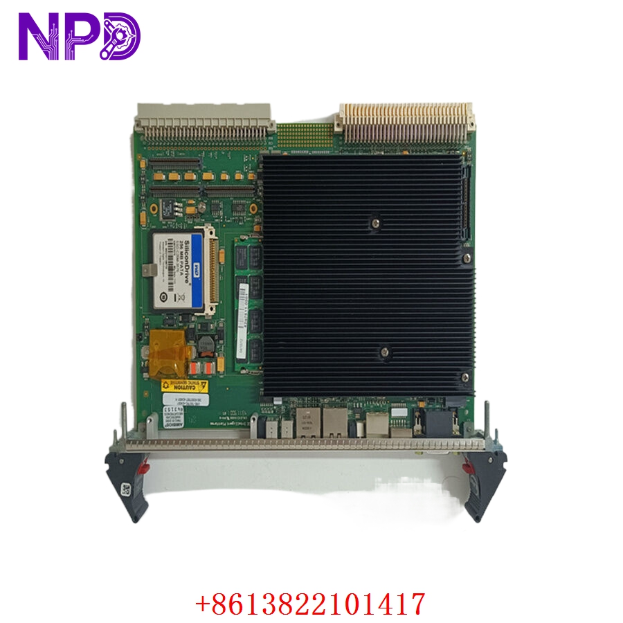

Description
The Böning AHD-882-CAN is a high-performance Data Gateway and Interface module designed for the integration of CAN bus-based data into complex marine automation systems. It serves as a vital bridge between various shipboard subsystems—such as engine controllers, navigation sensors, and alarm systems—and the Böning ship monitoring network. Its primary function is to translate and distribute data packets, ensuring seamless interoperability across the vessel’s control infrastructure.

📋 Technical Specifications
🔹 Part Number: AHD-882-CAN 🔹 Function: CAN Bus Data Gateway / Protocol Converter 🔹 System Series: Böning AHD (Automation and Monitoring System) 🔹 Input/Output: CAN bus interfaces (High-speed) 🔹 Operating Voltage: 24V DC 🔹 Weight: Approximately 0.40 kg 🔹 Origin: Germany
🚀 Application Fields
⚡ Marine Engine and Propulsion Monitoring ⚓ Integrated Bridge Automation Systems 🌊 Tank Monitoring and Valve Control ⚙️ Data Logging and Alarm Distribution
🛠️ Product Instructions
The AHD-882-CAN is typically housed within a central control cabinet or a local junction box. When installing, ensure that the CAN bus cables are shielded, twisted-pair cables designed specifically for high-speed industrial data communication. Proper termination—using 120-ohm resistors at the two physical ends of the CAN bus—is mandatory to prevent signal reflections that can cause data corruption. Secure the module onto a DIN rail and ensure the housing is correctly grounded to the ship’s common ground to maintain EMC integrity.
⚙️ Communication & Configuration Steps
⚙️ Address Mapping: The module requires configuration via the Böning “AHD-Config” tool. Each device on the CAN bus must have a unique identifier assigned to prevent data collision. ⚙️ Station Number: The station number is determined by the vessel’s specific network topography. This ensures the AHD-882-CAN correctly prioritizes incoming data from engine CPUs while passing outgoing alerts to the bridge displays. ⚙️ Baud Rate: The module supports standard marine CAN baud rates (typically 250 kbit/s). Ensure that all devices on the bus are configured to the same speed.
🔋 Power-up Debugging Process
✅ Step 1: Confirm that the 24V DC power supply is stable. ✅ Step 2: Observe the status LEDs. A constant green LED typically indicates the unit is powered, while a flickering LED indicates active data processing on the CAN bus. ✅ Step 3: Use the Böning service software to check the “Bus Load.” If the load is over 70-80%, check for misconfigured devices or “babbling” nodes on the network. ✅ Step 4: Check for CAN Error frames in the diagnostic log; if they are increasing rapidly, re-verify your bus termination and shielding.
📋 First-time Operation Checklist
✔️ Confirm the hardware version of the AHD-882-CAN matches the software requirements of your automation system. ✔️ Ensure all wiring harnesses are labeled and properly routed away from high-power AC lines to prevent interference. ✔️ Verify the bus termination resistance (120Ω) at the physical extremities of the bus. ✔️ Run a full “Node Scan” via the central configuration terminal to ensure the network discovers the new gateway successfully.
❓ Frequently Asked Questions (Q&A)
❓ Q: What happens if a node on the CAN bus fails? 💡 A: One of the strengths of the AHD-882-CAN is that the CAN bus protocol is designed for robustness. If one node fails, the rest of the network should continue to function; however, the gateway will log an error indicating the loss of the specific node.
❓ Q: Can I use this gateway to convert Modbus to CAN? 💡 A: Yes, the AHD-882-CAN acts as a protocol bridge. It can be configured to read Modbus data from connected devices and broadcast that information over the CAN bus for the rest of the Böning system to read.
❓ Q: How can I protect the module from voltage spikes? 💡 A: Always use an isolated power supply for your control electronics. Additionally, ensure the cabinet is fitted with appropriate surge protection devices on the incoming 24V supply lines to safeguard the sensitive internal CPU.