
Description
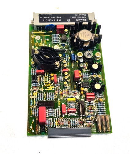
The Bosch Rexroth 0 811 405 011 is a precision analog amplifier card (specifically an electronic control module for proportional valves). It is designed to process command signals and provide the regulated output current necessary to control the position of a proportional valve’s spool, regulating hydraulic flow or pressure.
This card is a staple in legacy Rexroth hydraulic control loops. It uses onboard electronics to convert incoming voltage signals into precise PWM (Pulse Width Modulation) current, ensuring smooth, accurate, and repeatable motion for hydraulic actuators.
Technical Specifications & Features
| Parameter | Value/Description |
| Part Number | 0 811 405 011 |
| Component Type | Proportional Amplifier / Control Card |
| Input Signal | \pm 10V Command Signal |
| Supply Voltage | 24V DC |
| Output Type | PWM Current Output (Solenoid Drive) |
| Calibration | Manual potentiometers for Gain, Bias, and Dither |
| Mounting | Standard 19″ Rack-mount (Eurocard format) |
| Design | Analog logic (no digital interface/software) |
Common Setup Adjustments
Because this card uses analog circuitry, calibration is performed via front-panel potentiometers. Proper adjustment is vital to the health of your hydraulic system:
- Bias (Offset): Adjusts the input-to-output starting threshold. It is used to ensure the valve spool is at the exact center (closed) when a 0V command is present.
- Gain: Controls the sensitivity of the valve to your control input. High gain makes the valve responsive; too high can cause the system to oscillate (hunt).
- Dither: A critical adjustment for proportional valves. It adds a small high-frequency signal to the output to keep the valve spool in constant micro-motion, which prevents sticking (stiction) and ensures smooth low-speed performance.
Implementation & Maintenance Advice
Important Note: When replacing this card, there is no “digital backup” of parameters to download. You must ensure the new card is calibrated to match the specific hydraulic requirements of the valve it controls.
- Measure Before Removing: If the old card is partially functional, measure the voltage output on the solenoid test points or the specific potentiometer positions before removal.
- Environment: Ensure the card rack is free of conductive dust and that the cooling fans are functional. Excess heat is the primary killer of the electronic components on these legacy boards.
- Cable Shielding: Ensure the cable shield for the command signal (the \pm 10V wire) is properly grounded on the rack side only (to avoid ground loops) to prevent electrical noise from causing the hydraulic actuator to jump or jitter.