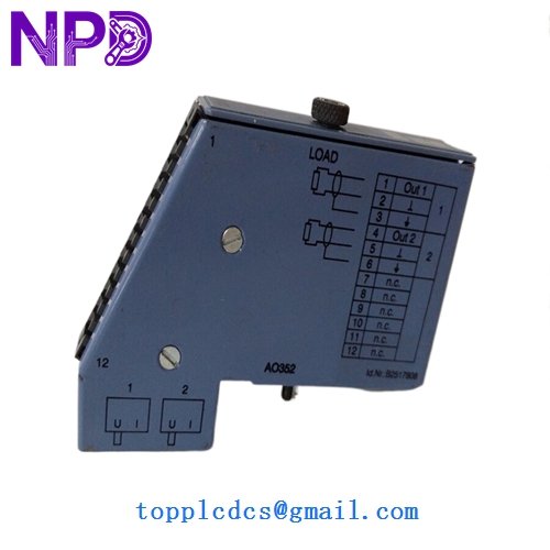


Description
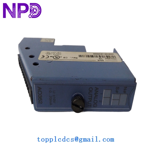
- Model: 7AO352.70
- Brand: B&R Automation (Austria)
- Series: System 2005 (Legacy Industrial I/O)
- Core Function: High-precision analog signal output for variable speed drives and valves
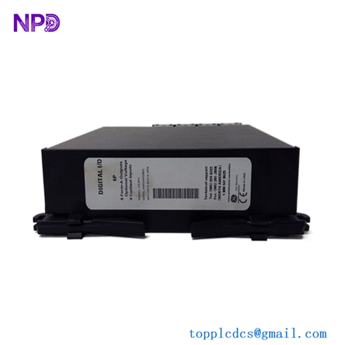
- Condition: Brand New Surplus (Original New), never used, factory seals intact
- Product Type: 2-Channel Analog Output Module
- Key Specs: 12-Bit Resolution | ±10 V or 0–20 mA (Jumper Configurable)
- Number of Outputs: 2 Channels
- Resolution: 12-bit (Binary)
- Output Ranges: ±10 V, 0 to 20 mA (Software/Hardware selectable)
- Galvanic Isolation: Yes (Between internal bus and outputs)
- Conversion Time: < 1 ms for both channels
- Current Load: Max 10 mA (Voltage output mode)
- Load Impedance: Max 500 Ω (Current output mode)
- Accuracy: ±0.1% of full scale at 25°C
- Status Indicators: 1 Status LED for module health
- Power Consumption: Approx. 1.5 W from the internal backplane
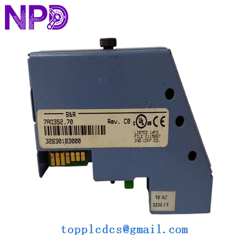
B&R 7AO352.70
Installation & Configuration Guide
Phase 1: Pre-Installation (Preparation: 15 minutes)
⚠️ Safety Protocol: The B&R System 2005 backplane is sensitive to static. Always use an ESD wrist strap. Ensure the PLC rack is powered down before inserting the module, as “hot-swapping” the 7AO352.70 can cause a bus error that stops the entire CPU.
Tools & Prep:
- Small flat-head screwdriver (2.5 mm)
- B&R Automation Studio (for hardware configuration check)
- Multimeter (to verify 0-10V or 4-20mA signals)
Phase 2: Configuration & Jumpers (Crucial: 10 minutes)
- Inspect Jumpers: Before mounting, check the side of the module. Unlike newer I/O, many 7AO352.70 units rely on physical jumper settings to toggle between Voltage (V) and Current (mA) modes.
- Match the Old Unit: Ensure the jumpers on the new module match the exact positions of the failed unit you just removed.
Phase 3: Mounting & Wiring (Installation: 20 minutes)
- Insertion: Slide the module into the designated slot on the System 2005 rack. Press firmly until the top and bottom latches engage.
- Terminal Connection: Reconnect the analog signal wires.
- Tip: Analog signals are susceptible to noise. Ensure the shielded cable is properly grounded at the entry point of the cabinet to prevent “signal jitter.”
- Tighten Screws: Secure the terminal block to the module face to ensure consistent electrical contact.
Phase 4: Software & Loop Test (Testing: 20 minutes)
- Power Up: Turn on the rack. The status LED should blink green or stay solid depending on the CPU state.
- I/O Mapping: In Automation Studio, verify the module is recognized in the hardware tree.
- Loop Test: Force a 50% output (e.g., 5V or 12mA). Use your multimeter at the terminal pins to verify the module is generating the correct signal before connecting it to the final actuator (like a VFD or proportional valve).
B&R 7AO352.70
Customer Cases & Industry Applications
Case 1: Plastic Injection Molding Recovery A high-speed injection molding machine in Mexico suddenly lost its ability to control clamping pressure. The fault was traced to a failed 7AO352.70 analog module. B&R had long since designated this part as “End-of-Life.” The factory faced a 3-week shutdown for a full control system overhaul. We provided a new surplus unit within 4 days. The factory avoided $120,000 in lost production and kept their existing machine running perfectly.
Case 2: Paper Mill Synchronization A paper mill used System 2005 for tension control between rollers. When an analog channel drifted out of calibration, the paper kept tearing. The maintenance team bought our 7AO352.70 as a “insurance policy” stock. Two months later, the original module failed completely during a night shift. Because they had our part on the shelf, the night shift electrician swapped it in 30 minutes, preventing a massive cleanup of torn paper pulp.
B&R 7AO352.70
Frequently Asked Questions (FAQ)
Q: Can I use this to replace a 7AO352.7? A: Yes. The “.70” suffix usually denotes a specific revision or packaging style, but functionally, the 7AO352.70 is the standard replacement for the 7AO352 series in System 2005 racks.
Q: My module shows a “Bus Error” LED. Is it dead? A: Not necessarily. In my experience, this often means the module isn’t seated perfectly in the backplane or there is a address conflict in Automation Studio. Try reseating it first. If the error persists, check the pins on the backplane for debris.
Q: Why not just buy a used one on eBay for $200? A: Honestly? Because analog outputs “wear out.” The capacitors and digital-to-analog converters (DACs) degrade over 20 years of heat. A used module might output 4.2mA when it’s supposed to be 4.0mA, causing your valves to leak or your motors to creep. Our New Surplus units at www.newplcdcs.com provide the precision you need for industrial-grade control.
Q: Does it come with the terminal block? A: Most of our surplus modules are sold as the base module only. If you need the screw terminal block (the “front connector”), please let us know so we can check if we have a matching one in stock to bundle with your order.