Description
⚓ Product Overview
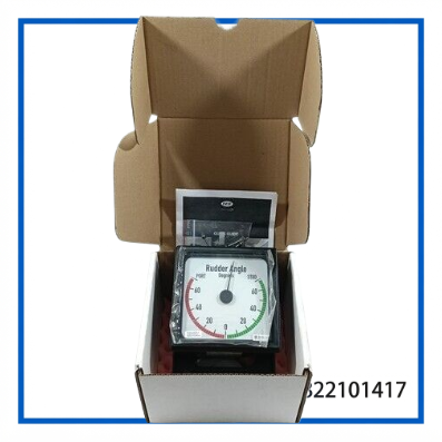
The DEIF BW144, part number 401010056.20, is a marine Bridge Wing Rudder Angle Indicator designed to provide clear visual indication of vessel rudder position.
The BW144 is designed for bridge-wing and tiller-compartment installation. It uses an analog indication format and is based on the DEIF XL indicator design, with a pivoting mounting arrangement, rear housing, and integrated dimmer for marine installation.
With a 24 V DC supply, ±10 V input, and ±45° indication range, the BW144 can be integrated into compatible ship steering and rudder feedback systems. An amplifier such as the TDG 210-DG is specified for the BW144 configuration.
🔹 Main Features
- ⚓ DEIF BW144 marine rudder angle indicator
- 🔹 Part Number: 401010056.20
- 🔹 XL144-related indicator design
- 🔹 Designed for bridge-wing and tiller-compartment mounting
- 🔹 24 V DC power supply
- 🔹 ±10 V analog input
- 🔹 ±45° rudder indication range
- 🔹 IP66 protection rating
- 🔹 Integrated dimmer
- 🔹 Easy adjustment
- 🔹 Suitable for marine steering and rudder indication systems
- 🔹 Amplifier required: TDG 210-DG
📊 Technical Datasheet
| Parameter | Specification |
|---|---|
| Brand | DEIF |
| Model | BW144 |
| Part Number | 401010056.20 |
| Related Model | XL144 |
| Product Name | Bridge Wing Rudder Angle Indicator |
| Product Type | Marine Rudder Angle Indicator |
| Power Supply | 24 V DC |
| Input | ±10 V |
| Indication Range | ±45° |
| Protection Rating | IP66 |
| Dimensions | 144 × 144 mm* |
| Operating Temperature | -25°C to +70°C* |
| Condition / Status | Marine Automation Spare Part — verify actual unit condition |
*Published BW144 specifications. The physical mounting envelope may vary depending on the specific housing configuration; verify the individual unit before replacement.
🧭 Marine Application
The BW144 is intended for applications where the helmsman or bridge personnel need a direct visual indication of rudder position.
Typical applications include:
- ⚓ Ship bridge wing steering stations
- 🚢 Tiller compartments
- 🛳️ Marine steering gear systems
- 🧭 Rudder position monitoring
- ⚙️ Steering gear feedback systems
- 🔧 Vessel automation maintenance
- 🔄 Replacement of existing DEIF/Data rudder indicators
The BW144 is specifically designed for flexible mounting and can be used in bridge-wing or tiller-compartment installations.
🔌 Electrical & System Integration
The BW144 accepts a ±10 V input signal representing rudder position and operates from a 24 V DC supply. The documented configuration specifies an external TDG 210-DG amplifier.
Before installation:
- Confirm the indicator model and part number.
- Verify the existing rudder feedback signal is compatible with the ±10 V input.
- Confirm the 24 V DC supply.
- Check the amplifier arrangement.
- Verify polarity and signal wiring.
- Compare the mechanical mounting arrangement with the existing indicator.
- Check the rudder-angle calibration after installation.
🛠️ Installation & Maintenance
The BW144 is intended for marine environments and has an IP66 protection rating. Even so, installation should protect the rear connections and cable entries from unnecessary mechanical stress and water exposure.
Recommended maintenance practices include:
- Inspect the front indicator and pointer for damage.
- Check mounting hardware periodically.
- Inspect cable glands and rear connections.
- Check for corrosion around terminals.
- Verify the 24 V DC supply.
- Confirm the analog rudder feedback signal.
- Check dimmer operation.
- Compare the indicated rudder position with the actual steering-system position.
- Recalibrate the indication if required by the steering system.
🔍 Troubleshooting
The pointer does not move
Check the 24 V DC supply, input signal, wiring, amplifier, and connector condition.
The indicated rudder angle is incorrect
Verify the ±10 V feedback signal and confirm that the indicator has been correctly adjusted or calibrated against the steering gear feedback.
The indicator moves in the wrong direction
Check input polarity and the signal assignment from the rudder feedback system.
The illumination or dimmer does not operate
Check the supply wiring and dimmer circuit. Inspect the housing and rear connections for moisture or corrosion.
The indicator operates intermittently
Inspect the analog signal wiring, terminals, connectors, power supply stability, and mechanical mounting. Marine vibration can also contribute to intermittent connection problems.
❓ Common Questions & Answers
Q: What is the DEIF BW144?
A: It is a marine bridge-wing rudder angle indicator designed to display vessel rudder position.
Q: What is the part number?
A: The supplied model is identified as 401010056.20.
Q: What is the power supply?
A: The BW144 specification is 24 V DC.
Q: What input signal does the BW144 use?
A: The documented BW144 configuration uses a ±10 V input.
Q: What is the indication range?
A: The specified range is ±45°.
Q: Is the BW144 suitable for bridge-wing installation?
A: Yes. The BW type is specifically designed for bridge-wing and tiller-compartment mounting.
Q: What is the protection rating?
A: The documented BW144 specification is IP66.
Q: Is an amplifier required?
A: The published BW144 specification identifies TDG 210-DG as the required amplifier.
🔧 Recommended DEIF Marine Models
- DEIF XL144 Rudder Angle Indicator
- DEIF BW144 Rudder Angle Indicator
- DEIF XL192 Rudder Angle Indicator
- DEIF BW192 Rudder Angle Indicator
- DEIF IAB19696/DH Rudder Angle Indicator
- DEIF TRI-2 Panoramic Rudder Angle Indicator
- DEIF TAB 40205 Rudder Feedback Unit
- DEIF TDG 210-DG Amplifier
- DEIF Marine Rudder Feedback Units
- DEIF Marine Steering Gear Indicators
📌 Replacement Note
For replacement purchasing, identify the complete assembly as DEIF BW144 / 401010056.20 / XL144-related Bridge Wing Rudder Angle Indicator. The most important compatibility checks are the 24 V DC supply, ±10 V input, ±45° indication range, mounting arrangement, amplifier configuration, and existing rudder feedback system.