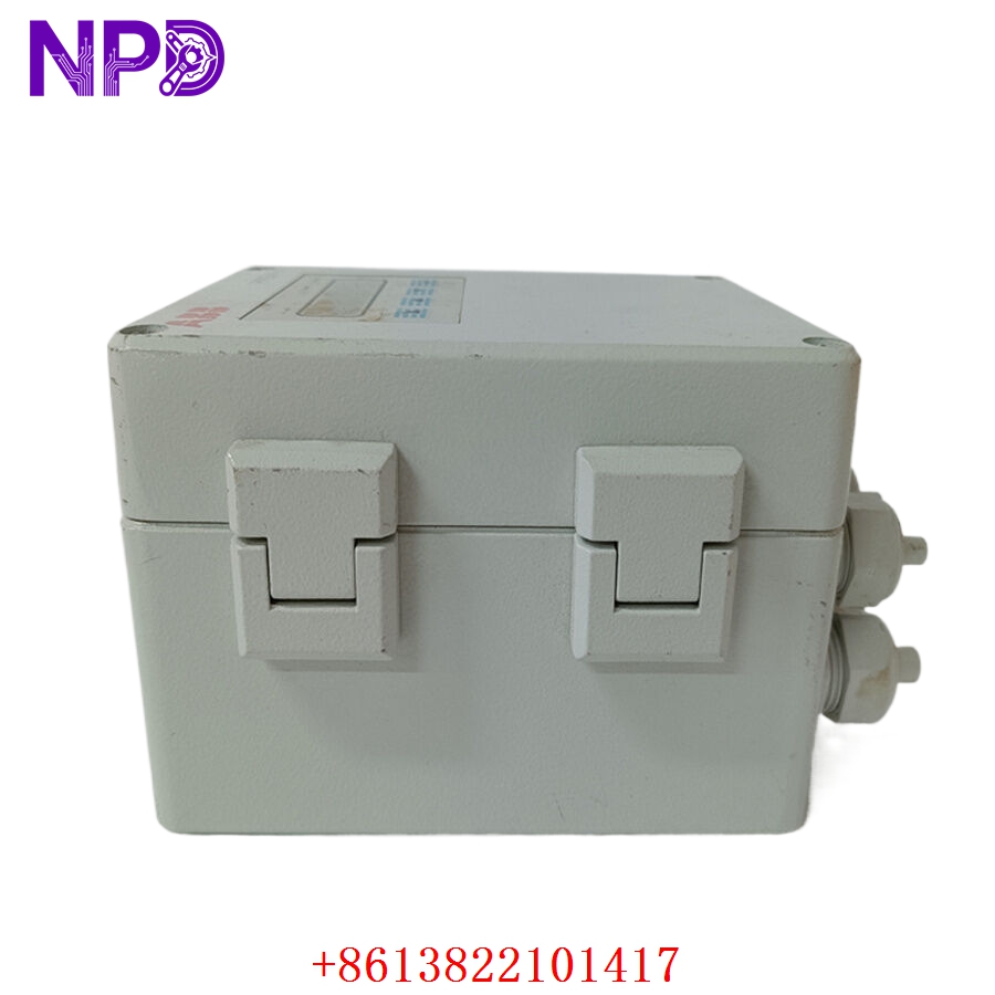

Description
The DEIF PCM 4.1 (Part Number: 1044230010K) is a high-precision Power Control Module designed for advanced energy management in multi-generator and grid-parallel power systems. It acts as the central coordinator for load sharing, synchronization, and power distribution management. By continuously monitoring electrical parameters and engine load, the PCM 4.1 ensures that generators operate at optimal efficiency, providing stable power delivery even under fluctuating load conditions in maritime, industrial, or standby power applications.
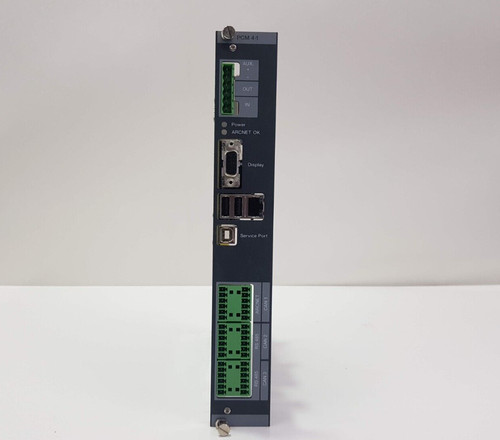
📋 Technical Specifications
- Model Number: 1044230010K
- Series: Power Control Module (PCM) 4.1
- Function: Generator Synchronization and Load Management
- Processor: High-performance real-time industrial processor
- Communication: Standard DEIF network protocols / CAN bus
- Dimensions: Standard modular controller housing (approx. 250 x 200 x 150 mm)
- Weight: 3.8 kg (8.4 lbs)
- Country of Origin: Denmark
⚙️ Application Areas
- Marine Vessel Power Plants
- Grid-Parallel Cogeneration Systems
- Data Center Standby Power
- Industrial Peak-Shaving Infrastructure
- Microgrid Power Distribution
🛠️ Operating Instructions & Guidelines
- Installation: Securely mount the module in an industrial-grade switchboard enclosure. Ensure all sensing leads (Voltage/Current) are properly fused and routed away from high-noise power cables. Proper grounding of the module chassis is mandatory for EMI compliance.
- Environmental Requirements: Keep the operating temperature within -25°C to +70°C. In marine applications, ensure the enclosure is effectively sealed against salt-laden air, which can cause internal board corrosion.
- Maintenance: Use the DEIF software interface to perform regular diagnostic checks and export system event logs. Periodically inspect the rear-terminal connections for signs of thermal oxidation.
⚡ Power Sequence & Operation
- Power-On Sequence: 1. Apply the 24VDC auxiliary control supply. 2. Observe the front display for the initialization sequence. 3. Verify that the communication link with other generators or the grid controller is established. 4. Perform a “System Health” check via the HMI to ensure all sensors are reporting valid data.
- Power-Off Sequence: 1. Open the generator circuit breaker via the control panel. 2. Bring the prime mover to a controlled stop. 3. De-energize the auxiliary control supply after the generator has fully stopped.
- Step-by-Step Operation: 1. Set the system mode (Automatic/Manual) based on the operational requirement. 2. Configure synchronization parameters, ensuring phase matching with the main busbar. 3. Monitor load sharing distribution on the graphical display. 4. Initiate the test cycle to verify that load shedding/addition sequences operate as configured.
❓ Frequently Asked Questions (Q&A)
- What is the main advantage of the PCM 4.1 over basic controllers? The PCM 4.1 provides superior “intelligence” for multi-engine systems, allowing for complex load-dependent start/stop sequences and precise reactive power sharing (VAr sharing) that simpler controllers cannot handle.
- How do I resolve a “Sync-Fail” error? Verify the voltage and frequency of the generator against the busbar using a secondary meter. If values are within limits, check the PT (Potential Transformer) connections for reversed polarity or phase rotation mismatches.
- Can this module communicate with third-party PLCs? Yes, the PCM 4.1 supports industry-standard communication protocols, allowing for integration into broader SCADA or building management systems.
- What does the “K” in the model number signify? This usually denotes a specific hardware version or regional compliance variant of the module, ensuring it meets specific maritime or industrial certifications.