
Description
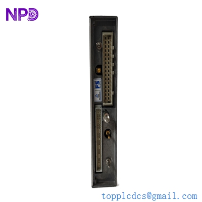
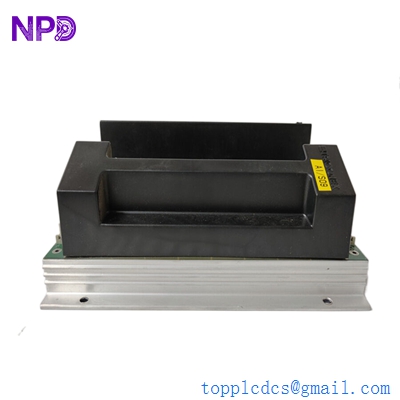
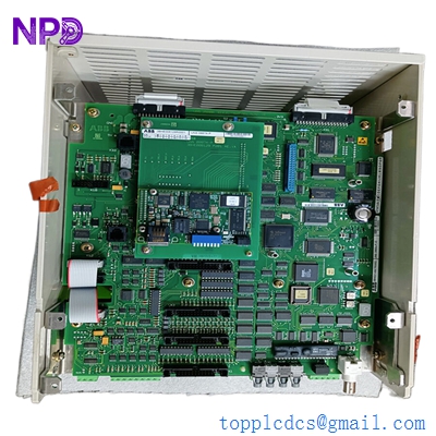
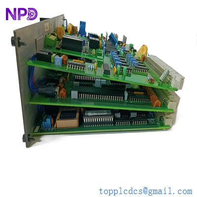
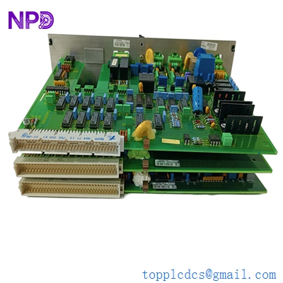
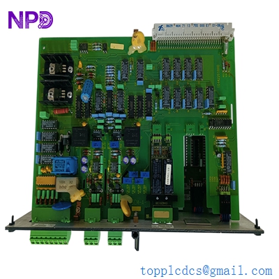
- Model: DEIF SCM-1 (Part No: 2912380010)
- Brand: DEIF (Denmark)
- Series: Multi-line 2 (ML-2) / AGC Series
- Core Function: Communication interface for power management and load sharing
- Product Type: Single Controller Management / Communication Module
- Key Specs: CANbus / RS-485 Interface 24 VDC Power Galvanic Isolation
- Supply Voltage: 12/24 VDC (Operating range 8–36 VDC)
- Communication Ports: Internal CANbus (for controller link) and External RS-485
- Protocol Support: Modbus RTU (Standard)
- Isolation: 2 kV AC between supply, communication, and relay outputs
- Mounting: DIN-rail (35 mm) or base mount
- Diagnostics: Power, Status, and Communication Error LEDs
- Baud Rate: Configurable up to 115.2 kbps for serial links
- Operating Temperature: -25 °C to +70 °C
- Protection Degree: IP20
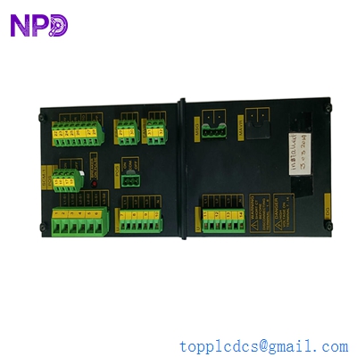
DEIF SCM-1
Application Scenarios & Pain Points
In my experience commissioning microgrids, the SCM-1 is the “diplomat” of the system. Its job is to ensure that a single generator controller can talk to the rest of the Power Management System (PMS). When you have a fleet of generators, if the SCM-1 fails, that specific genset becomes an “island”—it can run, but it won’t know how to share the load with its neighbors, leading to inefficient fuel use or, worse, a total bus collapse during a sudden load spike.
Typical Application Scenarios:
- Marine Power Management Used on vessels to link individual Generator Control Units (GCUs) to the main bridge monitoring system, ensuring balanced power across the switchboard.
- Data Center Backup Power Coordinating multiple standby diesel generators to ensure N+1 redundancy and seamless synchronization during a utility failure.
- Critical Infrastructure (Hospitals) Managing the load-sharing logic between emergency generators and the utility grid to prevent back-feeding.
- Remote Mining Sites Integrating renewable sources (Solar/Wind) with traditional diesel generation via the DEIF AGC platform.
Case Study: The “Blind” Generator
Background: A commercial container ship was reporting that Generator #3 would refuse to synchronize with the main bus, even though the voltage and frequency were perfect.
The Problem: After checking the DEIF AGC-3 controller, we saw a “Communication Error” alarm. The SCM-1 module’s internal CANbus transceiver had been damaged by a voltage surge on the 24V DC line. The controller couldn’t “see” the load levels of Generators #1 and #2, so it stayed in a safety lockout state.
The Solution: We replaced the SCM-1 and, more importantly, installed a dedicated DC/DC isolator for the control power. Since the SCM-1 is the bridge to the network, it’s often the first thing to fry when there’s a ground fault on the communication lines.
Result: Gen #3 synchronized in under 10 seconds on the first try. The vessel avoided a “heavy weather” delay by having full power capacity restored.
DEIF SCM-1
Compatible Replacement Models
The SCM-1 is a legacy workhorse. While newer AGC-150 or AGC-4 units have integrated comms, many older systems still rely on this external bridge.
| Model Number | Compatibility | Main Difference | Integration Note |
| SCM-1 (2912380010) | ✅ Direct | Standard version | Drop-in replacement for all ML-2 series. |
| SCM-2 | ❌ Incompatible | Dual controller management | Used for more complex redundancy; different pinout. |
| EIC 1.1 | ⚠️ Related | Engine Interface Card | Used for J1939 engine data; does not replace SCM-1 logic. |
DEIF SCM-1
Troubleshooting Quick Reference
| Symptom | Possible Cause | Relevance | Action |
| “Power” LED Off | Blown Fuse / No DC | ✅ High | Check for 24V DC at Terminals 1 and 2. |
| “Comm” LED Red | CANbus Wiring / Terminator | ✅ High | Ensure 120Ω resistors are at both ends of the CAN trunk. |
| Intermittent Connection | Ground Loop / Noise | ⚠️ Medium | Verify the RS-485 shield is grounded at the master only. |
| Controller “Link Fail” | Wrong Station ID | ⚠️ Medium | Use the DEIF Utility Software to match the Modbus ID to the PLC. |
Technical SOP & Quality Guarantee
Because DEIF modules are often used in mission-critical marine and hospital environments, our testing is exhaustive:
- Loop-Back Comms Test: We send Modbus packets through the RS-485 port and verify they are correctly translated to the internal CANbus protocol.
- Voltage Stress Test: We test the module at the upper and lower limits (8V and 36V) to ensure the internal regulators don’t drop out.
- LED Functionality: We verify every diagnostic LED is crisp and functional—on a dark ship or in a loud generator room, those lights are a tech’s only eyes.
- Terminal Block Integrity: We check the tension of every screw terminal to prevent “vibration-induced” failures, which are common in engine-mounted enclosures.
Engineer’s Advice: Honestly, when you install the new SCM-1, check your CANbus terminators. I’ve seen guys throw away perfectly good modules just because a 50-cent resistor was missing or loose. Measure the resistance across CAN-H and CAN-L with the power off; it should be exactly 60Ω if both ends are terminated correctly.