
Description
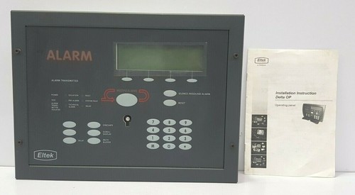
The ELTEK 251261.1 is a professional-grade Alarm Control Panel designed for high-reliability monitoring and notification in critical industrial and marine environments. As part of the Eltek safety and automation ecosystem, this panel provides real-time status reporting, fault detection, and alert management, ensuring operators maintain complete oversight of system health and safety parameters.
📋 Technical Specifications
🔹 Product ID: 251261.1 🔹 System Type: Alarm Monitoring and Control Panel 🔹 Operating Voltage: 24V DC 🔹 Mounting: Panel-mount / Flush-mount 🔹 Weight: Approximately 0.75 kg 🔹 Origin: Norway
🚀 Application Fields
⚡ Industrial Fire and Safety Systems ⚓ Maritime Alarm and Monitoring Systems 🏭 Emergency Shutdown and Notification Arrays ⚙️ Centralized Control Room Supervision
🛠️ Product Instructions
The 251261.1 is engineered for integration into control consoles. Install the unit in a secure, dust-protected location. Connect the power and communication cables to the rear terminals, ensuring that all connections are tight and stress-relieved. Since this device handles critical safety data, use shielded cabling to prevent electromagnetic interference from triggering false alarms.
⚙️ Communication & Configuration Steps
⚙️ Address Mapping: Use the configuration software or the unit’s internal setup menu to define the panel’s unique address within the alarm network. ⚙️ Station Number: Assign the station number according to the site’s specific I/O map, ensuring the central controller can uniquely identify and report alerts from this panel. ⚙️ Baud Rate: The communication speed is matched to the system bus requirements. Verify the settings in the technical manual to ensure seamless data exchange between the control panel and the main processing unit.
🔋 Power-up Debugging Process
✅ Step 1: Verify the input power polarity and voltage levels. ✅ Step 2: Power on the panel and monitor the “System Status” indicator to ensure it transitions from “Boot” to “Normal.” ✅ Step 3: Conduct a lamp test to confirm all display segments and indicators are fully functional. ✅ Step 4: Trigger a test signal from the central controller to verify successful communication link establishment.
📋 First-time Operation Checklist
✔️ Ensure all alarm labels and nomenclature are correctly positioned and visible. ✔️ Check that the external alarm buzzer is audible and its volume is appropriately configured. ✔️ Verify that the emergency power backup (UPS) is correctly wired to the panel’s power terminals. ✔️ Perform a full diagnostic loop test to ensure all connected sensors are communicating correctly with the panel.
❓ Frequently Asked Questions (Q&A)
❓ Q: How do I clear an active alarm on the panel? 💡 A: Press the “ACK” (Acknowledge) button to silence the audible alarm. Note that the alarm indicator will usually remain active until the underlying fault condition is resolved in the field.
❓ Q: What does a “Comm Fault” error imply? 💡 A: A “Comm Fault” indicates that the panel has lost its data connection to the main processing unit. Check the bus cables and termination resistors for damage or loose connections.
❓ Q: Can this panel be used for fire detection? 💡 A: Yes, the panel is designed for safety-critical applications; however, ensure your specific installation complies with local maritime or industrial fire safety regulations and standards.