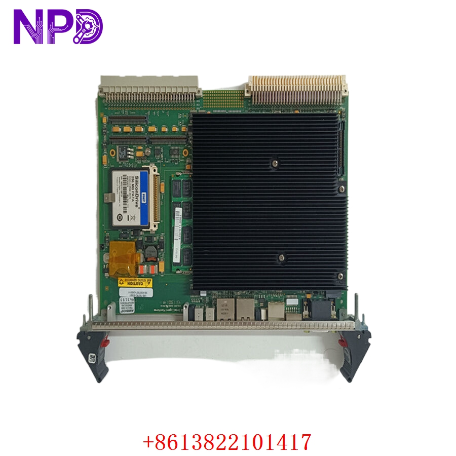

Description
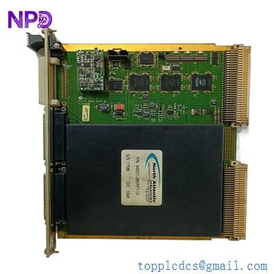
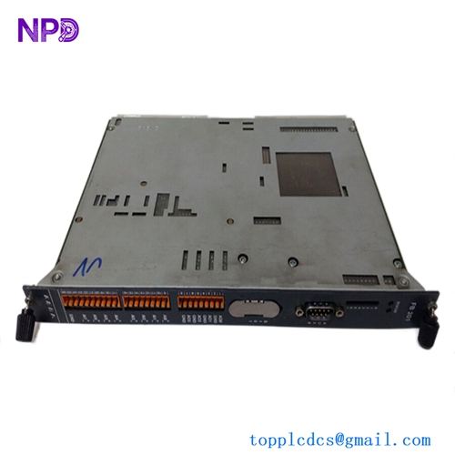
The ENRAF 42418040901 (PCB identifier M27310C) is a high-precision logic and processing card utilized in Enraf tank gauging systems. Designed for the oil, gas, and chemical storage sectors, this card manages critical level measurement data, providing the reliability needed for accurate inventory control and safety monitoring in terminal storage facilities.

📋 Technical Specifications
🔹 Part Number: 42418040901 🔹 PCB Identifier: M27310C 🔹 System Series: Enraf SmartRadar / Tank Gauging Series 🔹 Function: Sensor Signal Processing and Data Management 🔹 Weight: Approximately 0.35 kg 🔹 Origin: Netherlands
🚀 Application Fields
⚡ Tank Level Gauging and Inventory Management ⚓ Petrochemical Terminal Automation 🏭 Oil and Gas Storage Facilities ⚙️ Precision Flow and Pressure Monitoring
🛠️ Product Instructions
The M27310C card is housed within the electronics head of the Enraf tank gauge. To install, ensure the unit is completely isolated from power. Use a wrist strap to prevent ESD damage. Slide the PCB carefully into the internal mounting chassis and ensure all ribbon cable connectors are seated flush. Because these units are often in hazardous environments, verify that all seals and housing bolts are tightened to maintain the enclosure’s environmental/explosive-proof rating.
⚙️ Communication & Configuration Steps
⚙️ Address Mapping: The board’s address is typically configured via internal hardware jumpers or through the Enraf communication protocol during the “Setup” phase. ⚙️ Station Number: The station number identifies the tank gauge on the site’s communication bus (e.g., Enraf BPM protocol). This is set to match the configuration in your site’s tank management software. ⚙️ Baud Rate: Communication parameters are set to match the site’s field bus speed. Ensure that the bus line is correctly terminated with the appropriate resistor values to prevent signal reflection.
🔋 Power-up Debugging Process
✅ Step 1: Verify the 24V DC supply voltage at the gauge terminal block. ✅ Step 2: Apply power and watch for the “Status” LED on the M27310C card. A consistent blink pattern indicates successful self-initialization. ✅ Step 3: Use a diagnostic terminal to verify that the board is receiving raw data from the radar or servo level sensor. ✅ Step 4: Compare the local readout to the remote host system to ensure data packet integrity.
📋 First-time Operation Checklist
✔️ Confirm that the PCB part number (42418040901) matches the gauge hardware generation. ✔️ Inspect all internal cabling for signs of corrosion, which can occur in harsh storage terminal environments. ✔️ Verify that the board is seated firmly and that mounting screws provide a good ground path to the chassis. ✔️ Conduct a “Loop Test” to ensure level data is correctly transmitted to the control room.
❓ Frequently Asked Questions (Q&A)
❓ Q: Why does the unit show a “Comm Error” on the host computer? 💡 A: A communication error usually suggests that the card’s station address does not match the host’s configuration, or the bus cable has a short/open circuit. Check the wiring at the gauge junction box first.
❓ Q: Can I replace this PCB in an explosive zone? 💡 A: Only if you have a “Hot Work” permit and the enclosure is certified for maintenance in the specific zone. Otherwise, you must isolate the power and verify the area is gas-free before opening the housing.
❓ Q: Is the data on the board lost when I remove it? 💡 A: Most configuration settings are stored in non-volatile memory or on a separate module; however, always use a portable programmer to download the current tank configuration before replacing any internal PCB.