Description
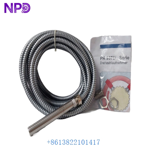
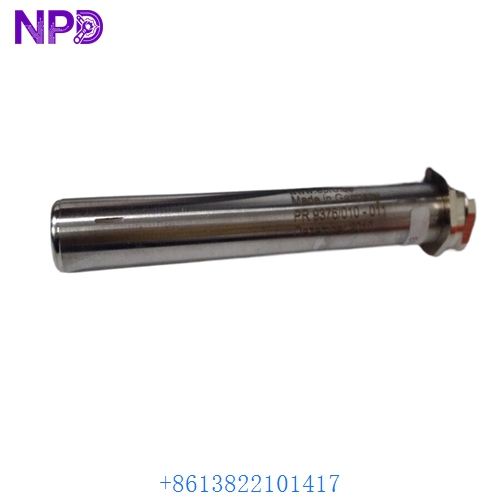
- Model: EPRO PR9376/010-011 (Material No: 9200-00097)
- Brand: EPRO (Emerson / Philips)
- Series: MMS 3000 / MMS 6000 Machine Monitoring Systems
- Core Function: Non-contact measurement of rotational speed and direction
- Type: Hall Effect Speed Sensor (Contactless)
- Key Specs: Dual-channel, push-pull output, frequency range up to 20 kHz
- Operating Principle: Differential Hall Effect (sensitive to ferromagnetic targets like gear wheels)
- Frequency Range: 0 Hz to 20,000 Hz (20 kHz)
- Air Gap (Sensing Distance): Typically 0.5 mm to 2.5 mm (Module dependent)
- Output Signal: Two square-wave signals (Channel A and B) shifted by 90° for direction sensing
- Output Stage: Push-Pull (Short-circuit proof)
- Supply Voltage: +10 V to +30 V DC
- Housing Material: Stainless steel (1.4305)
- Protection Class: IP67 (Hermetically sealed for oil/moisture resistance)
- Connection: Integral cable or connector (Standard version: 5-meter shielded cable)
- Operating Temp: -40°C to +120°C (-40°F to +248°F)
EPRO PR9376010-011 9200-00097
EPRO PR9376010-011 9200-00097
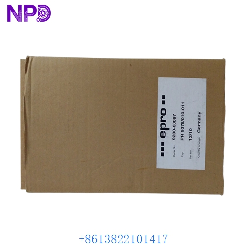
EPRO PR9376010-011 9200-00097
Installation & Configuration Guide
Phase 1: Preparation (15 minutes)
⚠️ Safety Warning: Speed sensors are often used in overspeed protection circuits. A failure to set the air gap correctly can result in a “Loss of Speed” signal, which may trigger an emergency turbine trip. Ensure the machine is at a standstill before adjusting the probe.
Required Items:
- Non-magnetic feeler gauges (Brass or Plastic).
- Digital Oscilloscope or Multimeter with frequency counter.
- Thread-locking compound (Loctite 243).
Phase 2: Physical Installation (20 minutes)
Steps:
- Clean the Target: Ensure the gear wheel or pole wheel is free of metal shavings or heavy grease buildup that could interfere with the magnetic flux.
- Gap Alignment: Thread the EPRO PR9376/010-011 into the mounting bracket. Use a feeler gauge to set the air gap to the manufacturer’s specification (usually 1.0 mm for standard gears).
- Orientation: For Hall Effect sensors, the orientation of the sensor head relative to the gear teeth is critical. Align the marking or “flat” on the sensor body parallel to the direction of rotation.
- Locking: Tighten the lock nuts and apply a small drop of thread-locker to prevent the sensor from backing out due to machine vibration.
Phase 3: Signal Verification (15 minutes)
Validation:
- Power Check: Verify +24 V DC is reaching the sensor.
- Static Test: With the machine stopped, the output should be a steady voltage (High or Low).
- Rotation Test: Rotate the shaft slowly (if possible). Use an oscilloscope to verify two clean square waves.
- Phase Shift: Check that Channel B lags or leads Channel A by approximately 90°. This confirms the sensor is correctly positioned to detect rotational direction.
Customer Cases & Industry Applications
Case 1: Gas Turbine Overspeed Protection
Situation: A power plant in Southeast Asia experienced “Speed Signal Fault” alarms on their Siemens turbine. The existing EPRO 9200-00097 sensor had a cracked cable housing, allowing oil ingress. Task: Replace the speed probe during a 4-hour window to prevent an automatic trip. Action: We dispatched a New Surplus unit from our stock via priority courier. Result: The new sensor provided a crystal-clear 18 kHz signal at full load. The plant avoided a trip that would have resulted in significant grid stability penalties.
Case 2: High-Speed Gearbox Monitoring
Situation: A compressor station used PR9376/010-011 sensors to monitor the input and output shafts of a high-speed gearbox. One sensor failed, leaving the system without direction-sensing logic. Task: Secure a brand-new sensor for a legacy MMS 3000 system. Action: The customer purchased a New Surplus unit to match their existing hardware revision exactly. Result: The “New Surplus” status ensured that the internal magnets and electronics were at 100% strength, providing reliable data for their predictive maintenance program.
Frequently Asked Questions (FAQ)
Q: Can I use the PR9376/010-011 to measure zero speed? A: Yes. Because this is a Hall Effect sensor (and not an inductive pickup), it can detect a gear tooth even when the shaft is not moving (0 Hz). This is critical for “Turning Gear” or “Barring” operations on large turbines.
Q: What is the difference between PR9376 and the older PR9375? A: The PR9376 (9200-00097) is a dual-channel sensor capable of direction detection, whereas the older PR9375 was often a single-channel speed-only probe. The PR9376 also features a more robust output driver for longer cable runs.
Q: Why buy “New Surplus” for a speed sensor? A: Speed sensors are exposed to extreme vibration and thermal cycling. A “Used” sensor may have micro-fractures in the internal potting or weakened cable stress reliefs. A New Surplus EPRO PR9376/010-011 offers the mechanical integrity of a new part, ensuring your overspeed protection system remains reliable.
Q: Does the sensor require a specific gear module? A: It is optimized for gear wheels with a module of 1.0 to 4.0. If your gear teeth are extremely small (Module < 1.0), the signal resolution may drop, requiring a smaller air gap.
Q: My signal is “noisy.” How can I fix it? A: In my experience, 90% of speed sensor noise is due to improper shielding. Ensure the cable shield is grounded at the monitor end only (MMS 6000 rack) and not at the sensor end. This prevents ground loops from distorting the pulse train.