Description
⚙️ Product Overview
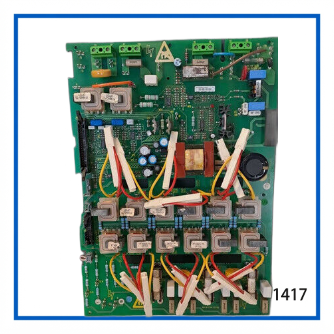
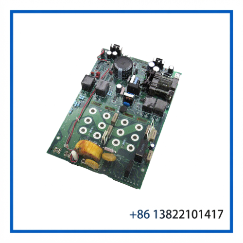
The Eurotherm AH352728U001 is a power supply board used in Eurotherm/Parker SSD Drives motor-control equipment. Available product references identify this part as a Power Board / Power Supply PCB for the 590SP DC drive platform. It provides internal power-supply functions required by the drive control electronics and interfaces with the main controller and power-stage circuitry.
The board is particularly relevant to maintenance and replacement work on legacy Eurotherm 590SP/591SP drive systems where maintaining the original power architecture is important. The AH352728U001 reference is also listed specifically as a 590SP power-supply PCB.
🔧 Key Features
- Manufacturer: Eurotherm / Eurotherm Drives
- Part Number: AH352728U001
- Board Type: Power Board / Power Supply PCB
- Associated Platform: Eurotherm 590SP / 591SP DC drive architecture
- Primary Function: Internal drive power-supply distribution
- Application: DC motor drive and industrial motion-control systems
- Electrical Architecture: Provides multiple internal DC supply rails for drive electronics
- Replacement Use: Suitable for maintenance, repair, and spare-parts inventory when the complete ordering code is matched
- Installation: Intended for integration inside the corresponding drive chassis
- Condition: Used, according to the supplied listing
📋 Product Datasheet
| Parameter | Specification |
|---|---|
| Brand | Eurotherm |
| Model / Part Number | AH352728U001 |
| Product Name | Power Board |
| Board Type | Power Supply PCB |
| Associated Drive Family | 590SP / 591SP |
| Manufacturer / Family | Eurotherm Drives / Parker SSD Drives |
| Input Supply | Configuration dependent; references identify 110–400 VAC for the 590SP power-supply assembly |
| Internal Outputs | Multiple DC rails for drive electronics |
| Typical Internal Rails | +24 V, +15 V, +5 V, 0 V, -15 V |
| Condition | Used |
| Country of Manufacture | Verify from individual board marking |
🔌 590SP Drive System Integration
The AH352728U001 is not a standalone general-purpose power supply. It forms part of the internal power architecture of the Eurotherm 590SP/591SP drive system.
In the documented drive architecture, the power-supply PCB provides several internal DC rails used by the control electronics. The system block diagram identifies connections associated with +24 V, +15 V, +5 V, 0 V and -15 V, together with control and monitoring functions such as main-supply status and SCR-firing circuitry.
This makes the board important when troubleshooting a drive that exhibits symptoms such as:
- Control electronics not powering correctly
- Missing internal supply voltages
- Drive initialization failure
- Incorrect power-status indications
- Intermittent controller operation
- Failure of associated control or firing circuits
⚡ Power and Control Functions
The AH352728U001 works within the drive’s internal power and control architecture rather than directly replacing the motor power stage.
Depending on the 590SP/591SP configuration, the surrounding system can include:
- Main AC supply connections
- Auxiliary control supply
- SCR firing circuitry
- Armature current measurement
- Field supply circuitry
- Motor armature connections
- Dynamic braking components
- Internal control-voltage distribution
The exact external power arrangement depends on the drive model, chassis configuration, and installed options. Therefore, the board’s part number should be matched against the existing drive assembly before installation.
🏭 Typical Applications
The AH352728U001 may be encountered in industrial DC drive systems used for:
- 🏭 Industrial machinery
- ⚙️ DC motor speed control
- 🏗️ Material-handling equipment
- 🧵 Process and converting machinery
- 🏭 Production-line equipment
- 🔄 Legacy motion-control systems
- 🔧 OEM equipment requiring Eurotherm 590SP/591SP service parts
For an existing installation, replacing the original board can be preferable to modifying the drive’s internal power architecture.
🛠️ Installation and Maintenance
Before replacing the board:
- Remove all incoming power from the drive.
- Allow the DC-link and internal capacitors to discharge completely.
- Confirm the absence of hazardous voltage with appropriate test equipment.
- Record connector positions and cable routing before removal.
- Compare the replacement board’s part number and revision with the installed board.
- Inspect connectors, terminal blocks, wiring, fuses, and surrounding components for evidence of overheating or contamination.
- Install the board without forcing connectors or PCB guides.
- Check grounding and protective connections before energizing the drive.
- Perform controlled power-up and verify the drive’s internal supply rails.
- Complete a functional test with the motor isolated or unloaded where appropriate.
⚠️ Because this is a power-supply board, failure of the original board may be caused by an external short circuit, failed power-stage component, wiring fault, or excessive load. Replacing the PCB without correcting the underlying fault can result in repeated failure.
🔍 Troubleshooting Guide
No control power after replacement
Check incoming supply, fuses, connectors, board seating, and the drive’s auxiliary power circuits.
Drive powers up but does not initialize
Check the internal supply rails and communication/control connections between the power board and controller circuitry.
Intermittent operation
Inspect connectors for oxidation, loose contacts, heat damage, and cracked solder joints. Also check whether the drive enclosure has excessive temperature or contamination.
Repeated board failure
Investigate downstream loads and the SCR/control circuitry before installing another replacement board.
Incorrect output voltage
Do not adjust or modify the board based only on a generic power-supply specification. Verify the expected voltage at the relevant test point using the correct Eurotherm drive documentation for the exact configuration.
❓ FAQ
What is Eurotherm AH352728U001?
It is a Eurotherm power board/power-supply PCB associated with the 590SP DC drive architecture.
Is AH352728U001 a complete DC drive?
No. It is a replacement PCB used inside the drive system.
What drive family is associated with this board?
References identify it with Eurotherm 590SP/591SP drive architectures. The exact compatible chassis and revision should be verified before ordering.
Can AH352728U001 be used in every Eurotherm 590SP drive?
Not automatically. Drive ratings, chassis versions, revisions, and internal configurations must be checked.
What should I check before ordering?
Compare the complete AH352728U001 part number, PCB markings, revision information, connector arrangement, and the original drive model.
Is the supplied item new or used?
The supplied listing identifies the board as used.
Can this board repair a drive with no control power?
It may be relevant, but no-power symptoms can also originate from fuses, incoming supply, wiring, downstream loads, or other drive components.
Does the board directly drive the motor?
No. It supports the internal power architecture of the drive; the drive’s SCR and associated power-stage circuitry handle motor power control.
Is the board suitable as a spare part?
Yes, provided the part number and drive configuration are correctly matched. It is especially useful for maintaining legacy Eurotherm DC-drive installations.
Should the original board be retained after replacement?
Yes. Keeping the original PCB can help with revision comparison, connector identification, and failure analysis.
🔄 Recommended Related Eurotherm Models & Components
- Eurotherm 590SP Digital DC Drive
- Eurotherm 591SP Digital DC Drive
- Eurotherm 590C DC Drive
- Eurotherm 591C DC Drive
- Eurotherm 590+ Digital DC Drive
- Eurotherm 590P Drive Controller
- Eurotherm AH470330U008 Power Board
- Eurotherm AH047833U002 Power Board
- Eurotherm AH385128U004 Control Card
- Eurotherm AH046990U010 Control Card
📦 Spare-Part Recommendation
For a legacy Eurotherm 590SP/591SP installation, the AH352728U001 Power Board should be treated as a critical electronic spare rather than a generic replacement PCB. Before installation, match the complete part number and board revision and inspect the associated drive power stage for the original failure cause.
For long-term maintenance, keeping one correctly matched spare power board in inventory can reduce downtime when a legacy DC drive experiences an internal power-supply failure.