Description
⚙️ Product Overview
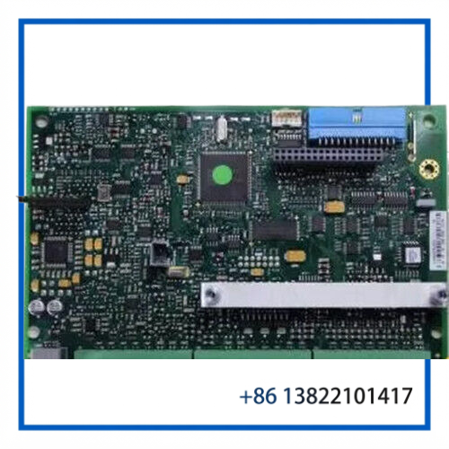
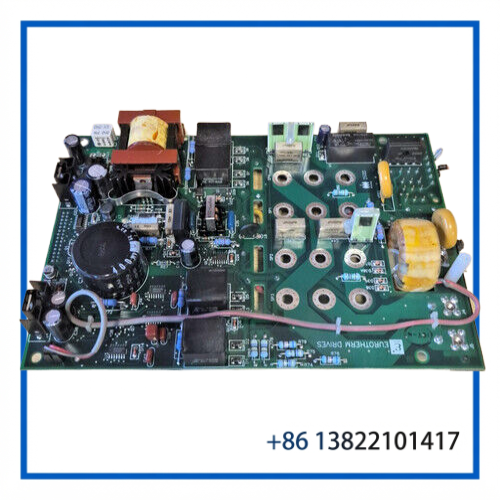
The Eurotherm Drives AH352728U001 is a Parker SSD Drives / Eurotherm power-supply PCB designed for the 590SP digital DC drive platform. The board is identified as the 590SP power-supply assembly and forms part of the drive chassis power architecture.
The AH352728U001 supplies the internal control-voltage rails required by the drive electronics and interfaces with associated start-relay, alarm-status, SCR-firing, and calibration circuitry. Drive documentation identifies the Power Supply PCB directly as AH352728U001.
This particular listing is identified as Issue 6.1, making the revision marking important when matching a replacement board to an installed drive.
🔧 Key Features
- Brand: Eurotherm Drives / Parker SSD Drives
- Part Number: AH352728U001
- Board Type: Power Board / Power Supply PCB
- Associated Drive: Eurotherm 590SP Digital DC Drive
- Revision: Issue 6.1
- Supply Range: 110–400 VAC
- Internal Supply Functions: Multiple regulated DC rails for drive electronics
- Typical Rails: +24 V, +15 V, +5 V, 0 V and -15 V
- Drive Architecture: 590SP DC motor controller chassis
- Condition: As listed, verify physical condition before installation
- Application: Industrial DC motor control and legacy drive maintenance
📋 Product Datasheet
| Parameter | Specification |
|---|---|
| Brand | Eurotherm Drives / Parker SSD Drives |
| Model / Part Number | AH352728U001 |
| Product Name | Power Board |
| Board Type | PCA Power Supply |
| Issue / Revision | Issue 6.1 |
| Associated Series | 590SP Digital DC Drive |
| Supply Range | 110–400 VAC |
| Internal DC Rails | +24 V, +15 V, +5 V, 0 V, -15 V |
| Condition | Verify against supplied unit |
| Country of Origin | Verify from board label |
🔌 590SP System Integration
The AH352728U001 is an internal power-supply assembly rather than a standalone AC/DC converter intended for general-purpose use.
Within the 590SP architecture, the power board supports several control supplies and connects with the drive’s internal control and power-stage circuitry. The documented 590SP LINK architecture shows the power board associated with the +24 V, +15 V, +5 V, 0 V and -15 V supply rails, as well as start-relay and main-supply-status functions.
The same architecture interfaces with SCR firing and armature-current calibration circuitry, so a power-board fault can affect several apparently unrelated drive functions.
⚡ Electrical & Control Functions
The 590SP system uses the power board as part of the internal electrical distribution system.
Depending on the drive configuration, associated functions include:
- Internal control-voltage generation
- Start-relay supply
- Main-supply-present monitoring
- SCR firing circuitry supply
- Armature-current calibration circuitry
- Pulse-transformer circuitry
- Control electronics supply
- Field and armature control system support
The 590SP documentation shows a single-phase control supply arrangement and identifies external auxiliary/control and field-supply connections around the power-supply PCB. Exact external wiring must be matched to the installed drive configuration rather than assumed from the PCB alone.
🏭 Typical Applications
The AH352728U001 is suitable for maintenance of legacy Eurotherm/Parker DC drive systems used in:
- 🏭 Industrial production machinery
- ⚙️ DC motor speed-control systems
- 🧵 Textile and converting equipment
- 📦 Material-handling machinery
- 🏗️ Process equipment
- 🔄 Industrial winding and unwinding systems
- 🔧 OEM machines using Eurotherm 590SP drives
For equipment that has been operating for many years, retaining a correctly matched power PCB can significantly reduce downtime when the original board fails.
🧩 Issue 6.1 Replacement Considerations
The Issue 6.1 marking should be recorded as part of the replacement process.
Do not determine interchangeability from the AH352728U001 number alone. Before installation, compare:
- Complete board part number.
- Issue/revision marking.
- Connector locations and designations.
- PCB component arrangement.
- Drive model and rating.
- Existing power-board wiring.
- Installed control-board revision.
- Any factory modification labels.
A replacement board that has the same basic part number but a different revision should be checked against the applicable drive documentation before being placed into service.
🛠️ Installation & Maintenance
⚠️ High-voltage safety is essential. The board is associated with a drive power system and should only be serviced by qualified personnel.
Recommended replacement procedure:
- Disconnect and isolate all incoming power.
- Apply the site’s electrical lockout/tagout procedure.
- Allow DC-link and internal capacitors to discharge.
- Verify zero voltage with suitable test equipment.
- Photograph or document connector positions before removal.
- Check the existing board for heat damage, burned components, contamination, or damaged connectors.
- Compare the replacement PCB with the original before installation.
- Confirm the Issue/revision marking.
- Reconnect all wiring according to the correct drive documentation.
- Inspect protective grounding and mechanical mounting.
- Perform a controlled power-up.
- Verify internal supply rails and drive status before returning the motor to normal operation.
🔍 Troubleshooting
Drive has no control power
Check incoming supply, protective devices, board connections, and the internal power-supply rails.
Some control functions work while others fail
Measure the relevant internal supply rails and inspect connectors. A missing supply rail can affect only part of the drive electronics.
Drive reports a supply-related fault
Check the main-supply detection circuit, auxiliary supply wiring, and power-board connections before replacing additional control boards.
Power board repeatedly fails
Do not immediately install another PCB. Investigate downstream loads, SCR circuitry, wiring faults, excessive temperature, and abnormal supply conditions.
Replacement board powers up but the drive still does not operate
The original fault may be located in the controller, SCR firing circuitry, current feedback, field circuit, or another connected assembly.
🔄 Recommended Related Eurotherm / Parker Models & Components
- Eurotherm 590SP Digital DC Drive
- Eurotherm 591SP Digital DC Drive
- Eurotherm 590C Digital DC Drive
- Eurotherm 591C Digital DC Drive
- Eurotherm 590+ Digital DC Drive
- Eurotherm 590P DC Drive
- Eurotherm AH385621U001 Power Board
- Eurotherm AH385851U002 Power Supply PCB
- Eurotherm AH047833U002 Power Board
- Eurotherm AH046990U010 Control Card
❓ FAQ
What is Eurotherm AH352728U001?
It is a power-supply PCB used in the Eurotherm/Parker 590SP DC drive architecture.
What does Issue 6.1 mean?
It identifies the board revision shown on the supplied unit. It is useful for matching the replacement to an existing installation.
What voltage range is associated with AH352728U001?
The part is identified for a 110–400 VAC supply range in Parker/Eurotherm spare-part references.
Which drive is AH352728U001 associated with?
The board is specifically identified as a power-supply PCB for the 590SP drive family.
Does it directly control the DC motor?
No. It supports the internal power and control architecture of the drive. Motor regulation involves the drive controller and SCR/power-stage circuitry.
Are all AH352728U001 boards interchangeable?
They should not be assumed interchangeable solely from the part number. Issue/revision, drive configuration, wiring, and installed hardware should be checked.
Is this a complete Eurotherm drive?
No. It is a replacement power-board assembly installed inside the drive system.
What should be checked before purchasing?
Compare the complete AH352728U001 number, Issue 6.1 marking, connector arrangement, original drive model, and board layout.
Can a defective power board cause multiple drive faults?
Yes. Because the board provides several internal supply rails, loss of one supply can affect multiple control and monitoring functions.
Is AH352728U001 useful as a maintenance spare?
Yes. It is a suitable inventory candidate for facilities operating compatible legacy 590SP equipment, provided the exact board revision and drive configuration are matched.
📦 Spare-Part Recommendation
For legacy Eurotherm 590SP installations, the AH352728U001 Issue 6.1 Power Board is a specialized maintenance spare rather than a generic replacement PCB. Its role in supplying multiple internal drive-voltage rails means a failure can prevent normal operation of the controller and associated firing/control circuits.
When stocking this part, record the complete part number, Issue 6.1 revision, original drive model, and board configuration together. This provides a much more reliable replacement reference for future maintenance than the part number alone.