
Description
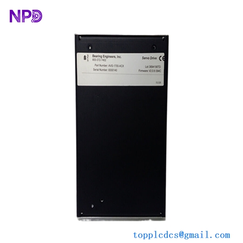
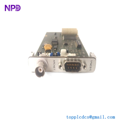
The FLOWSERVE 64-525-0006-31 and its associated assembly 64-525-0006-32 are high-precision encoder interface boards used within Flowserve digital positioners and electric actuator systems. This board functions as the primary feedback interface, converting mechanical rotary or linear movement into digital positioning data. It ensures that the valve actuator maintains precise alignment with the control signal, providing critical data for closed-loop modulation.
- Series Compatibility: Flowserve Limitorque and Logix Series Actuators
- Signal Type: Quadrature Encoder / Absolute Gray Code feedback
- Supply Voltage: 5V DC to 24V DC (provided by main controller)
- Resolution: High-resolution positioning for fine-tuned valve modulation
- Communication Interface: Dedicated digital bus to the main logic board
- Environmental Protection: Conformal coating for moisture and chemical resistance

Product Datasheet
| Feature | Specification |
|---|---|
| Model | FLOWSERVE 64-525-0006-31 |
| Assembly No. | 64-525-0006-32 |
| Dimensions | 115 x 75 x 18 mm |
| Weight | 0.12 kg |
| Country of Origin | USA |
| Connection Type | Multi-pin Ribbon Connector / Terminal Pins |
| Operating Temp | -40°C to +85°C |
Application Fields
This encoder board is essential for automated fluid control systems, particularly in:
- Chemical Processing: Monitoring precise valve positions for reactive chemical dosing.
- Oil & Gas Pipelines: Providing feedback for emergency shutdown valves (ESV) and flow control.
- Water Treatment: Managing the position of large-scale sluice gates and butterfly valves.
- Power Generation: Used in steam turbine bypass valves requiring high thermal stability and accuracy.
Product Instructions
- Safety Check: Power down the actuator and lock out the electrical supply before opening the housing.
- Access: Remove the actuator cover. Locate the feedback gear assembly where the encoder board is mounted.
- Removal: Carefully disconnect the wiring harness. Unscrew the mounting bolts holding the 64-525-0006-31 board, taking care not to disturb the alignment of the optical or magnetic sensor.
- Installation: Align the new board with the sensor shaft. Ensure the connector pins are straight before seating the harness.
- Re-Calibration: Once installed, the actuator must undergo a “Quick-Cal” or “Auto-Tune” procedure via the Flowserve handheld communicator or onboard interface to establish the zero and span positions.
Q&A – Common Questions
Q1: What is the difference between the -31 and -32 part numbers? A1: Typically, the -31 refers to the bare printed circuit board (PCB) component, while the -32 represents the full assembly, which may include the mounting bracket, specific connectors, or pre-installed firmware.
Q2: Can this board cause a “Position Feedback Error”? A2: Yes. If the encoder board fails or becomes fouled with debris, the actuator will lose track of its position, often triggering a “Feedback Fail” or “Stall” alarm on the digital display.
Q3: Is the board field-repairable? A3: Due to the high precision of the surface-mount components and the requirement for specific calibration, field repair of the board circuitry is not recommended. Replacement is the standard procedure for maintaining system reliability.
Related Product Recommendations
- Flowserve 64-525-0002-01 | Main Logic Controller Board
- Flowserve 135-520-0001-00 | Digital Positioner Display Module
- Limitorque 60-548-0051-4 | MX Series Power Board
- Flowserve 64-825-0006-10 | Network Communications Interface
- Flowserve 01-525-0045-02 | Potentiometer Feedback Assembly