
Description
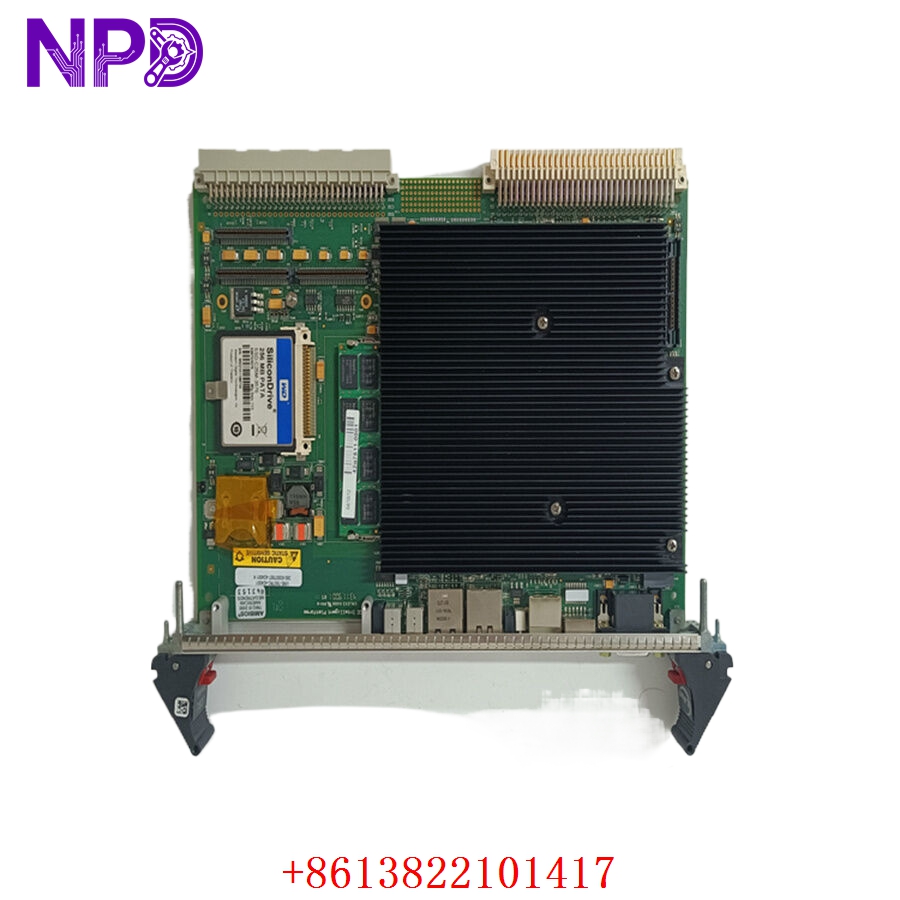
The FMC Energy Systems 2489930300P00 is a specialized Arm Control PCB board designed for high-precision motion control within marine loading arms and industrial fluid transfer systems. As a critical component in FMC’s automation architecture, this board processes positioning signals and safety logic to ensure the accurate, stable, and safe movement of articulated loading arms during fuel or chemical transfer operations.
📋 Technical Specifications
🔹 Part Number: 2489930300P00 🔹 Component Type: Arm Control Logic / Position Interface Board 🔹 Series: FMC Loading Arm Automation Series 🔹 Function: Arm Position Monitoring and Actuator Control Logic 🔹 Weight: Approximately 0.60 kg 🔹 Origin: USA
🚀 Application Fields
⚡ Marine Loading Arm Control ⚓ Bulk Fluid Transfer Automation 🏭 Industrial Petrochemical Loading ⚙️ Articulated Mechanical Positioning Systems

🛠️ Product Instructions
The 2489930300P00 board is intended for mounting within weather-proof, explosion-proof control enclosures. Before installation, verify the cabinet is isolated from power. Use anti-static precautions when handling the board to protect the sensitive logic controllers. Align the board carefully with the control rack pins; ensure all terminal wiring—especially those carrying positional feedback from encoders—is properly shielded to prevent signal distortion.
⚙️ Communication & Configuration Steps
⚙️ Address Mapping: System integration is performed via point-to-point wiring or a localized serial bus. Addressing is typically configured through physical DIP switches on the PCB to define the specific arm ID or node. ⚙️ Station Number: The station number is determined during the initial site commissioning by setting the switches to match the control software’s mapped I/O register. ⚙️ Signal Calibration: Calibration is achieved through onboard potentiometers used to set the “Gain” and “Offset” for the arm’s position transducers, ensuring that the software accurately reflects the physical angle of the arm.
🔋 Power-up Debugging Process
✅ Step 1: Verify the power input to the board (typically 24V DC). ✅ Step 2: Power on the system and observe the status LEDs; a steady green light indicates normal operation, while flashing red/yellow may indicate a position fault. ✅ Step 3: Use an engineering console or multi-meter to verify that the arm position transducer signal is reaching the board input terminals. ✅ Step 4: Command a small “test move” in manual mode to verify that the board sends the correct signals to the hydraulic/electric actuators.
📋 First-time Operation Checklist
✔️ Confirm the part number (2489930300P00) is the correct revision for your specific loading arm model. ✔️ Inspect all ribbon cables for signs of vibration-related wear or loose contact pins. ✔️ Verify that all safety limit switches (Hard Stops) are correctly connected to the board’s “Safety Interlock” input. ✔️ Perform a full diagnostic check on the arm’s position feedback loop to ensure smooth, jitter-free movement.
❓ Frequently Asked Questions (Q&A)
❓ Q: What does a “Position Error” on the control system mean? 💡 A: A position error typically means the PCB is receiving conflicting data from the arm’s sensors, or the actual position of the arm is outside the allowed software window. Check the transducer connection for signs of corrosion or moisture.
❓ Q: Can I use this board in a saltwater environment? 💡 A: Yes, but only if it is mounted within an original FMC-certified explosion-proof, moisture-sealed enclosure. Moisture ingress is the leading cause of premature failure for these PCBs in marine settings.
❓ Q: How often should I check the potentiometers for drift? 💡 A: If you notice the arm’s stopping position drifting over time, the board’s calibration potentiometers may require periodic adjustment. This should be done during your annual preventive maintenance cycle using the manufacturer’s calibration tool.