
Description
🔍 Product Overview
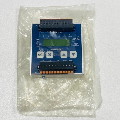
The Noris FMN6-1-11-K is a high-precision frequency transducer designed to measure and convert alternating current frequencies or speed pickup pulses into a standardized analog electrical signal. Part of the robust Noris FMN6 series, this module is widely utilized in maritime automation and heavy power generation systems to provide stable, real-time telemetry of speed and frequency variables to master PLCs, distributed control systems (DCS), or analog indicators. Its ruggedized design ensures high immunity to electromagnetic interference and mechanical vibrations, which are common in engine rooms and industrial electrical cabinets.
⚙️ Technical Parameters & Specifications
- Model Number: FMN6-1-11-K
- Device Type: Frequency to Analog Signal Transducer
- Input Configuration: 1-channel frequency input (optimized for tachometer generators, proximity switches, or AC voltage inputs)
- Output Signal Type: Standardized analog output (configured per variant, typically 4-20mA or 0-10V)
- Dimensions: 75 mm x 55 mm x 110 mm
- Weight: 0.38 kg
- Country of Origin: Germany
🚀 Application Areas
- Marine Diesel Propulsion: Converting magnetic speed pickup frequencies into engine RPM telemetry.
- Generator Frequency Monitoring: Tracking the output frequency of AC generators to ensure grid synchronization.
- Turbine Speed Controls: Delivering fast-response speed metrics for high-speed gas or steam turbine safety loops.
- Industrial Fan and Pump Monitoring: Interfacing shaft rotational metrics with variable frequency drives (VFD).
📖 Product Usage Instructions
The FMN6-1-11-K is designed for mounting on standard TS35 DIN rails within a protective control panel or terminal enclosure. Wire the raw frequency input lines (such as a 2-wire magnetic pickup sensor) to the designated input terminals using twisted, shielded instrumentation cables. Ensure that the signal shield is grounded at a single point inside the enclosure to eliminate ground loops. Maintain adequate physical spacing between the transducer and high-power switching contactors to prevent electromagnetic noise induction.
🌐 Communication Configuration Steps
- IP Address / Protocol Configuration: As a hardwired analog transducer, this device does not contain a native IP address or digital network protocol interface. It converts physical frequency metrics directly into proportional analog voltages or currents.
- Station Number: Physical station numbers or node addresses are not required. The device is mapped within the master control system according to the specific analog I/O channel terminal to which its output loop is wired.
- Baud Rate / Signal Scaling: Digital baud rates are not applicable. The analog scaling must be matched within the master PLC configuration software by mapping the minimum and maximum input frequencies (e.g., 0-10 kHz) to the corresponding analog span limits (e.g., 4-20mA).
⚡ Power-Up & Commissioning Flow
- Terminal Check: Verify that all screw terminals are tight and that the input signal lines and auxiliary power wires are correctly polarized.
- Supply Voltage Audit: Energize the auxiliary power line and confirm it meets the unit’s required ratings (typically 24V DC or standard AC auxiliary configurations depending on the exact terminal schematic).
- LED Check: Observe the front face panel. The green power indicator LED should illuminate steadily, signaling that the internal rail voltages are operational.
- Signal Injection Test: Use a frequency generator to inject a known test frequency into the input terminals and measure the analog output loop with a calibrated multimeter to confirm accurate scaling response.
✅ Initial Operation Checklist
- Is the transducer chassis securely snapped onto the DIN rail and tracking ground correctly?
- Are the input sensor signals shielded properly against ambient alternator hum and engine room interference?
- Has the output analog loop resistance been checked to ensure it falls within the transducer’s allowed load limits?
- Does the master controller HMI display match the actual physical frequency of the connected equipment?
❓ Common Questions (Q&A)
Q: What causes the analog output signal to drop to zero even when the machinery is spinning?
A: This typically points to an open circuit on the input sensor line, an incorrect clearance distance between the physical speed pickup and the target gear wheel, or the input frequency falling completely below the module’s minimum detection threshold.
Q: Can I adjust the zero-point and full-scale span values directly in the field?
A: Yes, the FMN6 series features integrated fine-tuning potentiometers accessible through the front faceplate cover. These allow technicians to perform minor recalibrations of the zero-point and maximum span metrics using an insulated trimming tool.
Q: Is it safe to leave the transducer powered if the input signal cable is disconnected?
A: Yes, the device is engineered with continuous short-circuit and open-circuit protection on both its input and output terminals, allowing it to safely remain in an idle powered state without sustaining internal component damage.