
Description
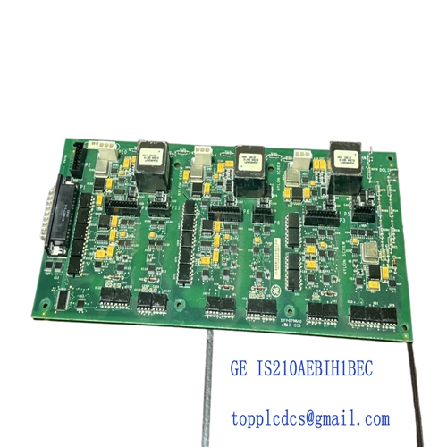
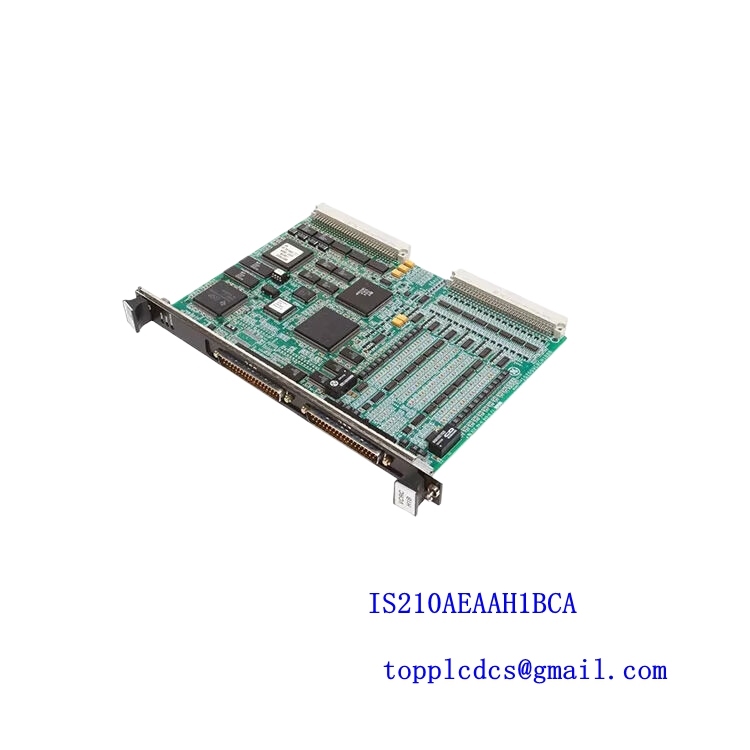
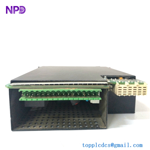
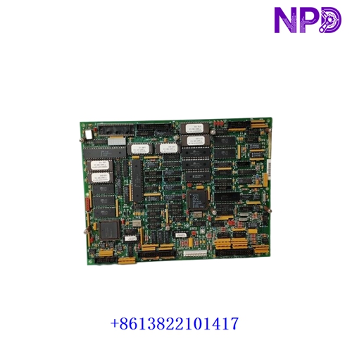
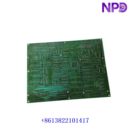
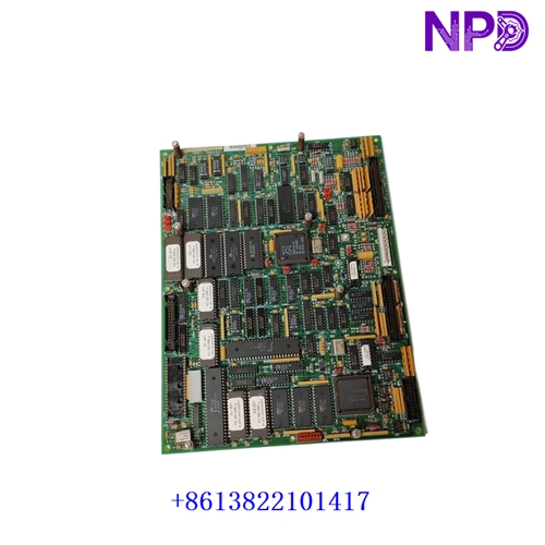
The GE 531X301DCCAFG2 (functionally designated as the DCC board) is the primary microprocessor-based Drive Control Card for General Electric industrial DC drives (such as the DC300, DC2000, and Siltron series) and generator excitation panels.
It executes closed-loop motor speed regulation, armature current loops, SCR firing pulse generation, and system diagnostic routines.
Technical Quick Reference
| Parameter | Specification |
| Manufacturer | General Electric (GE Power / GE Vernova) |
| Part / Revision Number | 531X301DCCAFG2 |
| Board Acronym | DCC (Drive Control Card) |
| System Compatibility | GE DC300, DC2000, Siltron, & Innovation Drive Racks |
| Power Requirements | +5V DC, ±15V DC, +24V DC (via power distribution board) |
| Onboard Storage | Socketed EPROM / EEPROM configuration chips |
| Feedback Types | Armature Voltage, DC Tachometer, Pulse Encoder |
| Operating Temperature | 0°C to +55°C (32°F to 131°F) |
Key Maintenance & Replacement Notes
- Firmware & Parameter Transfer: The board features socketed ICs containing drive-specific parameters and firmware. When swapping a failed board, the socketed EPROMs must be transferred from the old card to the replacement card using ESD-safe tools.
- Hardware Jumper Configuration: Jumpers on the DCC card establish signal scaling, feedback loop sources (tachometer vs. armature voltage), and interface modes. Verify all jumper positions match the original board configuration before restoring power.
- Diagnostic LED Indicators: Onboard LEDs indicate processor status, watchdog timer activity, and power supply health to assist in local fault isolation.