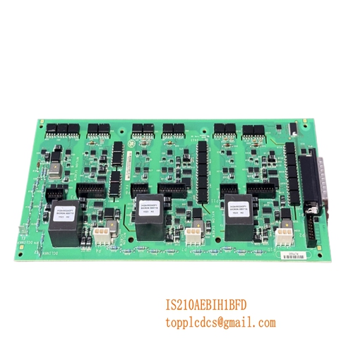
Description
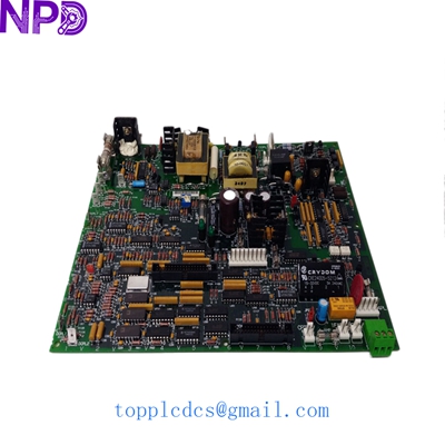
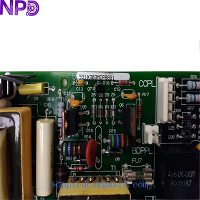
- Model: GE 531X303MCPBBG1 (Cross-ref: F31X303MCPAPG100600) · Brand: General Electric (GE) · Series: GE Drive Control / Motor Control Series · Core Function: High-precision motor control and signal processing board · Condition: Brand New Surplus (Original New), non-refurbished · Type: Printed Circuit Board (PCB) / Control Module · Key Specs: Multi-layer PCB Onboard Microprocessors Diagnostic LED Interface
- Application: DC/AC Drive Systems
- Input Voltage: Standard Logic Level (Internal Bus Powered)
- Connectivity: Multi-pin Ribbon Cable Connectors
- Operating Temp: 0°C to +55°C (32°F to 131°F)
- Storage Temp: -40°C to +70°C
- Humidity Range: 5% to 95% Non-condensing
- Mounting Type: Standoff / Rack Mount
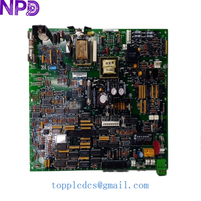
GE 531X303MCPBBG1 F31X303MCPA00200
Installation & Configuration Guide
Phase 1: Pre-Installation (Preparation)
Safety First:
- Verify the drive system is completely de-energized. Locked-out/Tagged-out (LOTO) procedures are mandatory.
- Wait at least 10 minutes for DC bus capacitors to discharge to safe levels (< 50 V).
- Ensure you have a grounded anti-static wrist strap. These GE boards are highly sensitive to ESD (Electrostatic Discharge).
Documentation:
- Take high-resolution photos of all wire harnesses and ribbon cables connected to the old board.
- Note any jumper settings (e.g., J1, J2) or DIP switch positions. Even identical part numbers might have site-specific configurations.
Phase 2: Removal of the Old Unit
- Labeling: Tag every connector before removal. In my experience, relying on memory for 10+ ribbon cables is a recipe for a “smoke test.”
- Disconnecting: Gently unplug cables. Use a small flat-head screwdriver to release retaining clips if necessary. Do not pull on the wires themselves.
- Unmounting: Remove the mounting screws/standoffs. Keep these in a magnetic tray; they are easily lost in the bottom of a drive cabinet.
Phase 3: Installing the New Board
- Comparison: Lay the new 531X303MCPBBG1 next to the old one. Verify that the hardware revision (the letter at the end of the part number) is compatible.
- Configuration: Transfer the jumper and DIP switch settings from the old board to the new one exactly.
- Seating: Align the board with the standoffs. Ensure no wires are pinched underneath. Tighten screws to approximately 0.4 N·m.
- Re-cabling: Reconnect all harnesses. You should feel a distinct “click” when ribbon cables seat properly.
Phase 4: Power-On & Testing
- Cold Check: Use a Fluke 115 or similar multimeter to check for shorts between the logic power rails and ground before applying AC power.
- Initial Power: Apply control power only (if separate from main power). Check the onboard LEDs. A green “Power” LED should be solid.
- Communication: If the board connects to a PLC or HMI, verify that the heartbeat signal is active and no “Module Missing” faults are present.
- Load Test: Gradually ramp up the motor speed while monitoring the drive parameters. Run for at least 60 minutes to ensure thermal stability.
GE 531X303MCPBBG1 F31X303MCPA00200
Customer Cases & Industry Applications
Case 1: Metal Processing Plant Emergency Repair
A steel mill in Pennsylvania experienced a sudden failure in their main rolling mill drive. The control board, an older F31X303MCPAPG100600, had suffered a capacitor leak. The plant was losing 12,000 per hour in idle labor and lost production. Since GE had labeled this part as obsolete, the local distributor quoted a 14-week lead time for a modern “retrofit” kit. We shipped a New Surplus board via Saturday Delivery. The mill was back online by Sunday evening, avoiding nearly 2 million in potential losses.
Case 2: Strategic Reserve for Paper Mill
A large pulp and paper facility in Southeast Asia operates several legacy GE drives. Recognizing that the 531X303MCPBBG1 is becoming increasingly difficult to find, the maintenance manager decided to perform an ABC analysis on their critical spares. They identified this board as a “Category A” item—high criticality, low availability. They purchased two units from our stock to keep as “insurance policies.” Six months later, one of their running boards failed due to an environmental overheat, and they swapped it out in 45 minutes with zero unplanned downtime.
Frequently Asked Questions (FAQ)
Q: What is the difference between the 531X and F31X part numbers? A: Functionally, they are often identical. The “F” prefix usually denotes a factory-assembled version or a specific packaging standard, while “531X” is the base catalog number. In 99% of applications, a 531X303MCPBBG1 is a direct, drop-in replacement for the F31X303MCPAPG100600.
Q: Is this board a “New Surplus” or “Refurbished” unit? A: We only deal in New Surplus. This means the board has never been installed in a machine. It may come from a cancelled project or a closed-down factory’s spare parts room. We do not sell “refurbished” boards because we cannot guarantee the remaining life of the individual components like electrolytic capacitors.
Q: Do I need to program this board? A: Most MCP (Main Control Processor) boards in this series hold firmware in EPROMs or Flash memory. If our board comes with chips installed, you should verify the version matches your system. In some cases, you may need to move the firmware chips from your old board to the new one.
Q: What if the board doesn’t work when it arrives? A: Every board undergoes a “Live Test” on our simulation rack before shipping. However, if it fails to initialize, we offer a 7-day DOA (Dead on Arrival) exchange policy and a full 1-year warranty for hardware defects. Just send us a photo of the error code or LED status.
GE 531X303MCPBBG1 F31X303MCPA00200
Related Inventory Models
- ABB 3BSE008508R1
- GE IS215UCVEH2AE
- Bently Nevada 3500/22M
- Triconex 3625
- Honeywell MC-TAMT03
- Siemens 6DD1607-0AA2
- Allen-Bradley 1756-L73
- Fanuc A06B-6079-H106
For more technical data and real-time availability, please visit newplcdcs www.newplcdcs.com.