
Description
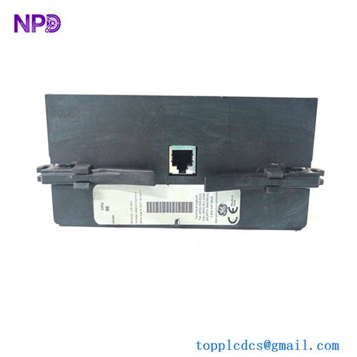
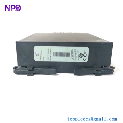
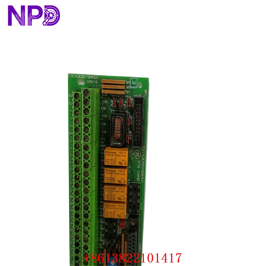
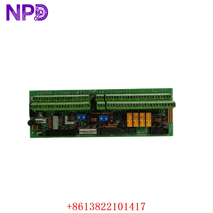
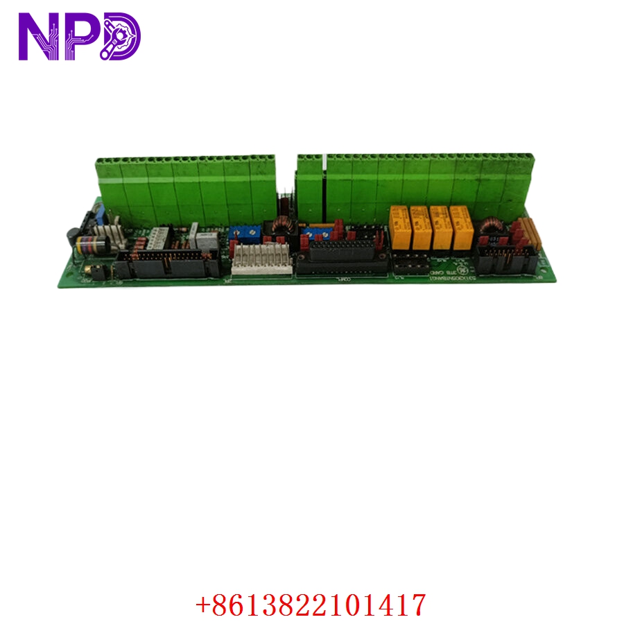
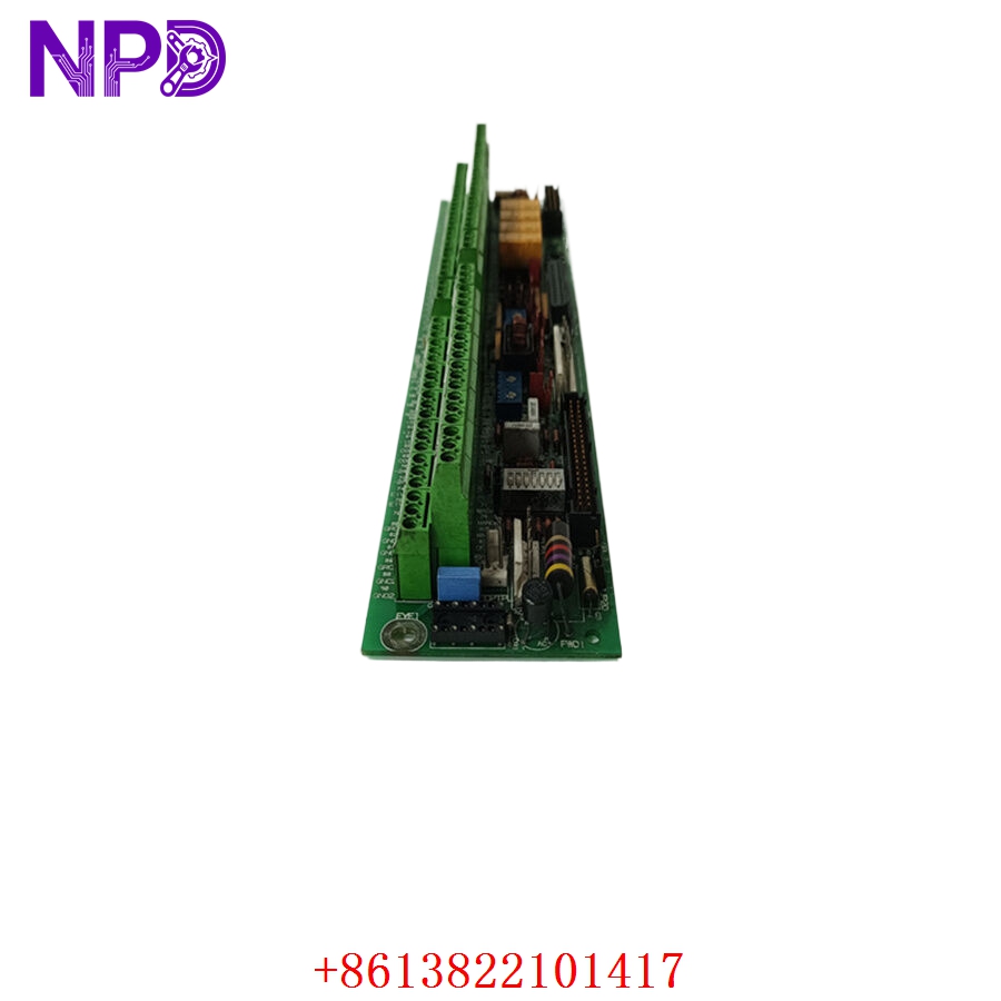
- Model: GE 531X305NTBANG1 (Functional equivalent: F31X305NTBANG1)
- Brand: GE (General Electric – USA)
- Series: Innovation Series / Direct Digital Control (DDC) Drive Systems
- Core Function: Main termination and signal attenuation board mapping external field I/O to the drive control core
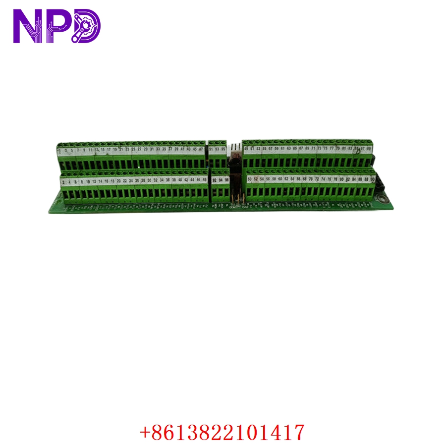
- Product Type: NTBAN Termination Board / Terminal Block Assembly
- Key Specs: 7x Analog Inputs | 4x Analog Outputs | Integrated Noise Attenuation Filters
- Operating Power Supply: Powered via internal drive backplane connector ribbons
- Board Classification: NTBAN termination block configuration
- Total Signal Channels: Multi-channel discrete and analog interface processing array
- Analog Input Mapping: 7x dedicated diagnostic analog inputs (voltage/current range determined by drive parameters)
- Analog Output Mapping: 4x configurable analog output monitoring ports
- Terminal Interface Layout: Heavy-duty screw-type terminal blocks accepting 12 to 22 AWG field wiring
- Physical Form Factor: Rectangular open-frame board designed for direct backplate or drive-cabinet mounting
- Noise Filtering: Onboard passive RC network attenuation circuits on signal pathways
- Compatibility Matrices: Fits legacy GE Innovation Series AC/DC drives and related heavy industrial exciters
Application Scenarios & Engineering Pitfalls
The On-Site Reality
If you are managing automation systems in heavy continuous-process facilities—such as a multi-stand hot rolling steel mill or a paper mill web-tension line—you know exactly what happens when a termination board goes south. The 531X305NTBANG1 acts as the physical terminal bridge where sensitive field inputs meet high-speed processing logic. When these legacy termination paths crack from years of cabinet vibration or degrade from chemical corrosion, your drive control processor loses its eyes and ears. Finding an exact replacement through standard factory channels is next to impossible due to its mature lifecycle status, threatening to keep critical machinery down for weeks.
Typical Deployment Scenarios
- Metal Processing – Hot/Cold Rolling Mill Stand Drives
Routes high-resolution tachometer and tension feedback loops into the main controller, demanding low latency and high noise immunity from nearby high-current switchgear.
- Paper and Pulp – Multi-Section Web Paper Machine Controls
Handles critical draw and speed-matching analog control links where any signal drift directly causes sheet breaks and operational downtime.
- Mining & Material Handling – Main Overland Belt Conveyor Inverters
Interfaces external pulling-switches, thermal sensors, and safety interlocks directly into the drive brain across long field distances.
- Marine Automation – Diesel-Electric Vessel Propulsion Excitation
Manages governor interface signals and voltage feedback loops within harsh, high-vibration engine-room drive cabinets.
Plant Survival Case Study: Unplanned Rolling Mill Shutdown Averted
- Background: A midwestern steel processing plant running a heavy GE Innovation Series DC drive on their primary roughing stand experienced erratic speed deviations, eventually triggering a hard “Analog Input Fault” shutdown.
- The Problem: Field technicians traced the issue to corrupted tachometer feedback signals. The original 531X305NTBANG1 termination board had developed micro-cracks on the copper traces under terminal block group 3 due to decades of structural vibration. The plant was losing production capacity at a rate of tens of thousands of dollars per hour, and the local OEM branch reported that the part number was completely unsupported by current production lines.
- The Solution: The plant’s automation lead contacted our facility to tap into our tested legacy surplus stock. We pulled a clean 531X305NTBANG1 unit, ran it through our comprehensive multi-channel signal injection verification protocol, and shipped it out via priority air freight within hours.
- The Result: The replacement board was delivered to the mill floor the next morning. The field crew mounted the board, transferred the wiring harnesses, and brought the roughing stand back to full operational speed by noon—saving days of potential production backlogs.
Compatible Replacement Models
In legacy system preservation, understanding part number prefixes and engineering suffixes prevents costly purchasing errors. Below is the compatibility roadmap for this specific terminal board family:
| Original Part Number | Alternative Model | Compatibility Level | Key Differences / Structural Variances | Required On-Site Modification Steps | Cost Variance |
| 531X305NTBANG1 | F31X305NTBANG1 | ✅ Drop-in Replacement | Functional equivalence; “F” prefix designates an updated manufacturing run with identical fit, form, and function. | Direct swap. No software changes, parameter modifications, or rewiring required. | Baseline Cost |
| 531X305NTBANG1 | 531X305NTBANA1 | ⚠️ Software Compatible | Earlier revision group (A1). Lacks specific noise filtering optimization added to the G1 revision. | Check if field cabling requires external shielding adjustments to mitigate electrical noise if used in high-EMI environments. | -10% |
| 531X305NTBANG1 | 531X309NTB_ _ _ | ❌ Hardware Incompatible | Different board layout family designed for alternative drive horsepower frames or control configurations. | Physical dimension mismatches and altered ribbon connector pin assignments. Do not attempt retrofit. | +30% |
Quality Assurance & Testing Standard Operating Procedure
To eliminate any reliability concerns regarding “new old stock” or legacy spare parts, every single board goes through a documented, step-by-step technical inspection before it receives shipping clearance.
[Inbound Traceability Check] ➔ [Microscopic Solder/Trace Audit] ➔ [Passive Component Metering] ➔ [Multi-Channel Signal Injection Loop] ➔ [Anti-Static Shielded Desiccant Packing] 1. Source Traceability and Visual Screening
- History Verification: Cross-referencing board batch numbers to confirm authentic GE fabrication origins and verify compliance with industrial revision histories.
- Structural Check: Detailed examination for any signs of physical board cracking, terminal screw stripping, or substrate delamination around high-stress mounting points.
2. Microscopic Trace and Solder Joint Integrity Audit
- Joint Analysis: High-magnification optical inspection of surface solder joints, searching for cold joints, micro-fractures, or oxidation built up over extended storage.
- Terminal Integrity: Ensuring the rugged screw terminals are mechanically sound and free of internal carbon tracking or pitting.
3. Passive Component Metering
- Component Testing: Utilizing an LCR meter to check onboard RC filtering networks (resistors and capacitors) against nominal design values.
- Variance Detection: Any board exhibiting component degradation, drying out of electrolytic materials, or parameter drift beyond original tolerances is immediately pulled from circulation.
4. Live Multi-Channel Signal Injection Simulation
- The Testing Environment: The board is connected to a live testing array mimicking the ribbon cable interfaces of a functioning GE Innovation Series control rack.
- Loop Tests: We inject known analog values (4 to 20 mA and 0 to 10 VDC) through every single field terminal path, monitoring the output data stream at the control bus connector to guarantee perfect signal attenuation and tracking accuracy.
- Continuity Checks: Cycling all discrete pathways to ensure clean transitions without signal dropouts or cross-channel bleeding.
5. Final Quality Sign-Off and ESD Packaging
- Tagging: The inspecting technician signs and applies a serialized “QC Passed” label directly to the anti-static packaging.
- Shielding Protocol: Sealed inside a moisture-resistant, static-shielding bag accompanied by fresh desiccant packs, then secured in shock-absorbent foam inside a durable industrial shipping container.
Legacy Terminal Board Field Troubleshooting Quick Reference
❗ SAFETY FIRST: Disconnect and lock out all main incoming three-phase power lines feeding the drive system before handling internal boards or loosening any terminal connections. Verify all DC bus capacitors have completely discharged down to 0 V using a verified, high-voltage voltmeter.
Q: The drive controller sporadically loses analog feedback values, causing the system to trip out under load, but the feedback values return to normal when the drive is idle.
A: Correlation: High. This behavior points to mechanical trace failures or weak terminal clamping on the 531X305NTBANG1 board. Under load, high-current structural vibrations can cause tiny, hairline fractures in older copper traces or loose terminal screws to briefly open up, dropping the signal.
- Shut down the power.
- Use a torque screwdriver to check every terminal point.
- Gently tap the board chassis while monitoring loop resistance with a digital multimeter to see if you can trigger the open circuit. If the resistance fluctuates wildly during a physical tap, replace the board.
Q: After transferring field wiring to the termination board, an analog channel shows a completely flatline value at the controller level, even though the field instrument is active.
A: Correlation: Medium-High. The passive RC noise filtering circuit or surge protection diode on that specific board channel might have blown due to an external field wiring short circuit or lightning strike.
- Use a standard multimeter to check signal continuity from the terminal screw right to the corresponding pin on the ribbon cable header.
- If the signal pathway measures as completely open or dead shorted to the board ground trace while other channels read normally, the input path on the board is compromised. Swap the card for a verified spare.
Q: The drive boots up but displays a comprehensive “Control Interface Ribbon Fault” and refuses to accept any remote commands.
A: Correlation: Medium. This error can be caused by either a bad multi-pin ribbon cable or a problem with the header socket on the 531X305NTBANG1 board itself.
- Inspect the female ribbon cable sockets for bent, corroded, or pushed-back pins.
- Clean the contacts with a high-purity electrical contact cleaner.
- If the error persists after swapping the ribbon cable with a known-good assembly, the multi-pin header on the termination board has failed internally, requiring a card replacement.
❗ Essential Installation Guidelines for the Maintenance Team
- Labeling Prior to Disconnection: Never disconnect field wires based on memory. This board has numerous parallel analog and digital input landings. Use wrap-around wire labels to mark every single conductor according to its terminal designation before loosening a single screw.
- Ribbon Cable Alignment: Ensure the high-density ribbon cables are completely seated and that the side locking ears click into place perfectly. A slightly skewed ribbon connector can cause erratic drive control faults that are incredibly difficult to track down during commissioning.
- Shield Continuity Management: Ensure all incoming instrument shielded drains are terminated properly at the designated chassis grounding strip, not tied to signal common points. Improper shield landings on the termination board will introduce severe electrical noise into the drive’s main control processor.