Description
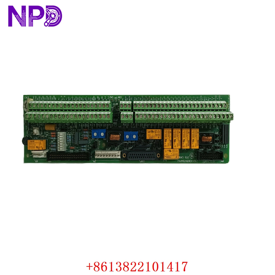
- Model: GE 531X305NTBAPG1 (Alternate PN: F31X305NTBAPG1 / Manufacturing No: MRP375547)
- Brand: General Electric (USA)
- Series: EX2000 Excitation System & AC/DC2000 Drive Series
- Core Function: Interfaces external I/O signals with the drive control board, Original New Surplus condition
- Type: NTB/3TB Main Terminal Board
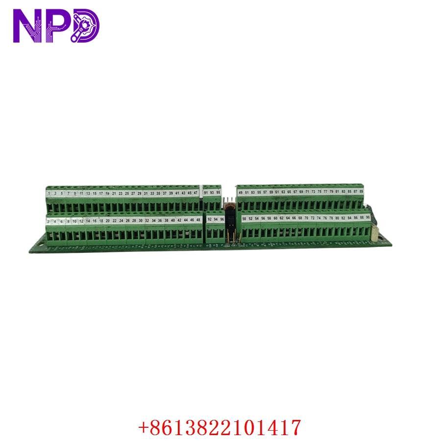
- Key Specs: 95 I/O Connection Terminals | 7 Onboard Relays | Optically Isolated Encoder Interface
- Total Terminals: 95 point terminal block connectors
- Regulated Outputs: +5 V DC (300 mA), +15 V DC (300 mA)
- Unregulated DC Output: 24 V DC (500 mA)
- AC Output Capacity: 120 V AC (0.5 A max capacity)
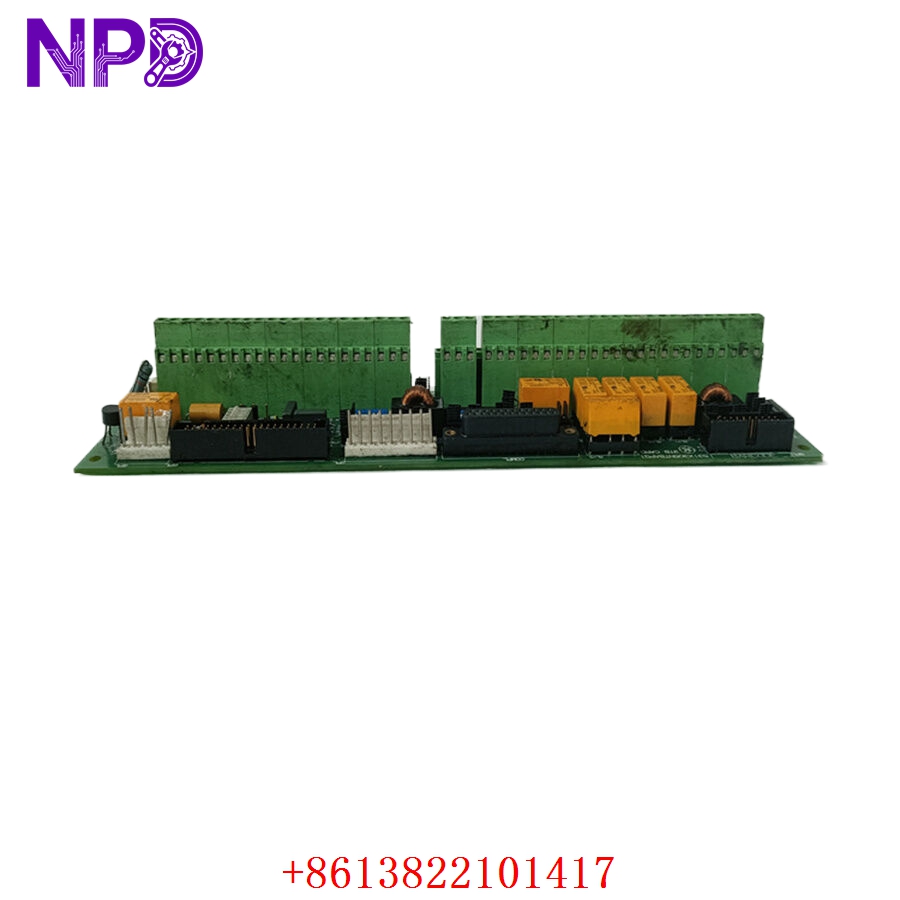
- Onboard Relays: 7 total (Form A and Form C configurations rated at 120 VAC)
- Encoder Interface: Differential A-quad-B encoder with integrated marker channel
- Optical Isolation: Fully isolated on the drive control interface side
- Analog Adjustment: 4 onboard potentiometers for low-level analog I/O scaling
- Digital Inputs: 12 general purpose 24 V DC control inputs (including Reset/Control On)
- Serial Links: RS-232C / RS-422 communications routing
- Associated Document Manual: GEI-100020B reference standard
Part 4: Installation & Configuration Guide
Phase 1: Pre-Installation (Estimated Time: 20 minutes)
⚠️ Safety First:
- Contact operations management to coordinate a scheduled shutdown window for the turbine or drive cabinet line.
- Confirm that the excitation system has entered an unexcited state, and trip the upstream feeder breakers.
- Lock out and tag out (LOTO) all AC power feeds entering the cabinet, specifically checking auxiliary 120 V AC supply links.
- Wait a full 10-15 minutes. High-power drives carry residual charge in the DC bus capacitors. Attempting maintenance immediately can cause fatal arc-flash or instant board destruction.
Tool Preparation:
- ESD grounding wrist strap and static-dissipative work mat
- Small precision flathead screwdriver for terminal blocks
- Phillips screwdriver for housing mounting
- Fluke 115 Digital Multimeter
- Marker tags and high-resolution camera
Backup Procedures:
- Extract current drive parameters using the cabinet keypad or system console software. Store a master copy on an external data drive.
- Take high-resolution photos of the 95 screw terminal configurations and jumper clusters (J1 through J20+) to verify physical orientation before un-wiring.
Phase 2: Removal (Estimated Time: 25 minutes)
Steps:
- Verify using your multimeter that the DC bus test points register under 24 V DC and the 120 V AC terminal arrays are dead.
- Unplug the internal communications ribbons: plugs 6PL and 8PL linking to the drive control board, and plugs 2PL/4PL connected to the power supply.
- Label each external field cable group systematically.
- Carefully back out the screw terminals one by one to free the input/output field lines. Lift the wires straight out without wrenching the back board.
- Extract the perimeter mounting screws holding the PCB card to the cabinet chassis standoffs.
- Handle the board exclusively by its edges and slide it free of its seating, putting it inside an ESD shielding container immediately.
⚠️ Key Notes:
- Field terminal assignments often change between custom site setups; relying entirely on standard manual drawings without site tags can ruin your field signal routing on re-assembly.
Phase 3: Installation (Estimated Time: 30 minutes)
Steps:
- ESD Protection: Anchor your grounding wrist strap before opening the protective packaging of the new surplus 531X305NTBAPG1 board.
- Jumper Calibration: Carefully inspect every onboard hardware jumper on the new card. You must adjust these to mirror your old board settings exactly. These jumpers govern whether your digital inputs use positive/negative logic, scale analog signals, and determine if your optical encoder uses +5 V or 15 V power.
- Chassis Seating: Position the board over the mounting standoffs inside the exciter cabinet. Secure all screws, taking care not to over-tighten, which can cause micro-cracks in the multilayer PCB traces.
- Re-wiring Field Terminals: Route all 95 terminal positions back to their matching wires using your tags and photos. Tighten down the screw clips to anchor the bare conductors securely.
- Re-attach Internal Plugs: Plug 6PL, 8PL, 2PL, 4PL, and COMPL back into their matching keys, confirming the locking tabs click shut.
Self-Check Checklist:
- [ ] Hardware jumper maps on the new card mirror the decommissioned unit exactly
- [ ] No stray copper wire strands bridging adjacent terminals among the 95 points
- [ ] Ribbon cables fully seated with zero skewing
- [ ] Potentiometers pre-adjusted to match legacy scaling settings
Phase 4: Power-On & Testing (Estimated Time: 25 minutes)
Pre-Power Checks:
- Measure insulation resistance between terminal blocks and chassis ground using your multimeter. Ensure there are no dead grounds on the 24 V DC or 120 V AC distributions.
Power-On Steps:
- Energize the auxiliary control power lines only (leave the primary excitation power isolated).
- Monitor the drive display. The control board should acknowledge the terminal board without generating an external fault code.
- Voltages Verification: Probe the regulated power checkpoints on the terminal card. Confirm that +5 V DC and +15 V DC test points fall within a tight \pm2\% margin. Check that unregulated 24 V DC is stable.
- Test the digital input states: Manually initiate a ‘RESET’ and ‘CONTROL ON’ pulse from the field panel and track the input registry status.
- Dynamic Check: Re-engage main excitation power. Initiate a low-load operational cycle, validating that encoder feedback reads out smoothly via the differential channels and that the 4 analog scaling pots behave stably.
- Log the maintenance entry with the replacement serial number for tracking inventory turnover.
Part 5: Customer Cases & Industry Applications
Case 1: Critical Turbine Overhaul at a Thermal Power Plant
Situation:
A thermal power plant running a vintage GE steam turbine utilizes the EX2000 excitation framework to control power grid synchronization. During an un-scheduled grid load fluctuation, an external inductive surge fed directly into the exciter cabinet, bypassing isolating relays and frying the internal terminal trace path on the main 531X305NTBAPG1 board, resulting in a sudden unit trip.
Task:
The plant went dark instantly, costing thousands of dollars per hour in idle grid capacity fees. The engineering department checked legacy supply lines, only to find that GE had categorized the component as obsolete years ago, meaning standard distributor networks quoted lead times of 8 to 12 weeks to source refurbished alternatives from secondary global depots.
Action:
The plant’s asset recovery team reached out to our logistics hub. We pulled an original new surplus F31X305NTBAPG1 terminal board directly from our sterile stock holdings. To secure trust, we mounted the board onto our internal test bed, verified the isolation limits of the onboard relays, checked the outputs of the 5V/15V regulators, and shipped the part via priority overnight air courier.
Result:
- Downtime Cleared: The package reached the plant site within 18 hours of the initial fault. The crew duplicated the complex jumper profile and finished wiring the 95 connections before noon.
- Capital Protection: The turbine re-synchronized successfully on the first attempt, preventing an extended outage window that would have cost the enterprise substantial contract penalties.
- Customer Voice: “Honestly, finding an un-used board for a legacy EX2000 system on short notice seemed impossible. Most vendors offer dirty used components with 30-day guarantees. Receiving a pristine, un-opened board with real test records saved our plant timeline.”
Case 2: Preventive Component Sourcing for a Steel Rolling Mill
Situation:
A heavy steel fabrication facility relies on an AC/DC2000 drive package to control a massive hot rolling mill. The main drive cabinet depends on the 531X305NTBAPG1 NTB/3TB interface board to manage high-speed differential encoder tracking and field relay triggers under intense heat and ambient vibration.
Task:
The facility’s reliability engineer noticed that the onboard scaling potentiometers on the existing card were beginning to drift due to long-term exposure to thermal cycling, causing minor speed oscillations in the roller motors. Knowing that a complete terminal board breakdown would stall the main mill line, procurement needed an original, un-degraded replacement card immediately to minimize obsolescence write-offs.
Action:
The mill contacted us to secure an authentic, un-used piece before the market supply vanished entirely. We supplied an authentic MRP375547 / 531X305NTBAPG1 card in its sealed protective wrap, complete with factory serial numbers, letting the client cross-reference the batch authenticity before making changes to their equipment.
Result:
- Reliability Restored: The mill scheduled a planned 2-hour maintenance window over the weekend to drop in our surplus card. The motor oscillations ceased immediately once the clean onboard pots were tuned.
- Strategic Insurance: By replacing the drifting card before total structural failure, the plant avoided an unpredictable breakdown during high-output operational windows.
- Long-term Value: The maintenance division booked the component with a 12-month warranty, extending the production viability of their capital equipment for several more years without requiring a million-dollar drive upgrade.
Part 6: Frequently Asked Questions (FAQ)
Q1: What is the structural difference between part numbers 531X305NTBAPG1 and F31X305NTBAPG1?
A: They are the exact same electronic assembly. The “531X” designation represents the catalog prefix used by GE’s drive components division during initial assembly distribution. The “F31X” format is the manufacturing code variant used on the circuit board silkscreen layers and schematic prints.
If your old board shows either number on its barcode label or printed frame, this New Surplus component will drop in as an exact match without needing changes to your cabinetry or brackets.
Q2: Why is it vital to copy the jumper clusters (J1-J20) from our old terminal board before swapping?
A: The 531X305NTBAPG1 is a highly versatile interface board designed to handle a wide range of external devices. It uses physical jumpers to configure its circuits for different needs.
For example, these jumpers determine whether the board expects a +5 V or a +15 V differential encoder signal, and they set up the internal bias resistors for positive or negative control logic on the 12 digital inputs.
If you install a new board with stock factory jumper placements without matching your old board’s specific layout, you risk sending the wrong voltage to your field equipment or misinterpreting critical safety signals like ‘RESET’ or ‘CONTROL ON’. Always copy the original board’s jumper layout exactly.
Q3: Are the onboard relays and potentiometers pre-calibrated when shipped?
A: The 7 integrated relays (Form A and C rated at 120 VAC) are completely tested and ready to use out of the box. However, the 4 analog scaling potentiometers are set to standard neutral factory defaults.
Because every drive setup uses distinct scaling parameters for low-level analog inputs and outputs, you must measure the resistance profiles of the pots on your old board or monitor your drive’s signal readouts during commissioning to tune these adjustments to your specific loop requirements.
Q4: Your inventory pricing sits below factory lists, yet you state it isn’t refurbished. How is this possible?
A: We realize that low prices for obsolete components can look suspicious. Our pricing model reflects efficient inventory procurement, not lower quality:
- Overstock Acquisition: We purchase surplus equipment directly from corporate liquidations, plant closures, or un-used project overstock that companies need to clear off their balance sheets.
- No Middlemen Markups: We avoid multiple distributor layers and sell directly from our stock holdings, keeping our overhead low.
- No Hidden Cleanup: Unlike repair shops that buy broken boards, patch the visible burns, and sell them as refurbished, we only sell un-used components that pass rigorous functional testing on our own equipment.
Q5: How do you protect this sensitive multilayer board against shipping damage and ESD?
A: We follow strict industrial handling procedures. The 531X305NTBAPG1 contains static-sensitive CMOS tracking circuits that can be damaged by improper handling before installation.