

Description
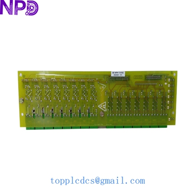
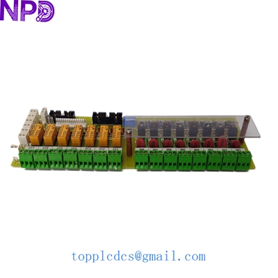
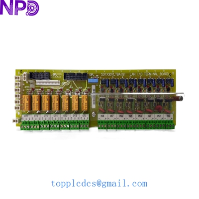
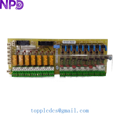
- Model: GE 531X307LTBAJG1
- Brand: General Electric (GE)
- Series: Mark V / Innovation Series
- Core Function: Local Area Network (LAN) Terminal and Termination Board
- Product Type: Terminal Board / Interface Module
- Key Specs: Dual LAN port support | Passive & Active termination components | High-reliability connectors
- Voltage Rating: Low voltage signal level (Logic/Bus powered)
- LAN Type: Compatible with GE DLAN and DLAN+ protocols
- Connection Interface: 2 x 9-pin D-sub or specialized header (revision dependent)
- Termination Impedance: Precision matched for bus stability
- Mounting Style: Bolt-on standoff mount within the control cabinet
- PCB Coating: Standard industrial conformal coating for moisture resistance
- Dimensions: Standard GE Small Form Factor (SFF) board
- Compatibility: Integrated with UC2000 and Mark V control architectures
- Operating Temp: 0 to 60°C (32 to 140°F)
- Isolation: Galvanic isolation between communication segments
GE 531X307LTBAJG1
Installation & Configuration Guide
Stage 1: Pre-Installation
⚠️ Safety Protocols:
- System Lockout: Ensure the drive system is in a “Safe” or “Local” mode before disconnecting communication boards.
- Power Down: While this is a signal board, it is connected to sensitive logic circuits. Power off the control rack to prevent “glitch” signals from triggering an emergency trip on adjacent modules.
- ESD Precautions: Use a grounded wrist strap. The termination resistors and ICs on the 531X307LTBAJG1 are sensitive to high-voltage static discharge.
Tools Required:
- Small flat-head screwdriver (for terminal blocks)
- 1/4″ Nut driver or Phillips head (for mounting standoffs)
- Isopropyl alcohol and lint-free wipes (for cleaning port contacts)
Stage 2: Removal
Steps:
- Identify Bus Position: Note if this board is at the “End of Line” (EOL) or a “Mid-node.” This affects how jumpers are set.
- Cable Disconnection: Gently unscrew the D-sub connectors. If using ribbon cables, pull the ejection tabs rather than the cable itself.
- Unmount: Remove the four corner screws. Keep the nylon standoffs; they prevent the board from shorting against the metal backplane.
Stage 3: Installation
Steps:
- Jumper Configuration (Critical):
- Check the J1/J2 Jumpers. These typically enable or disable the termination resistors.
- If this is the last board on the LAN chain, the termination must be ON. If it is in the middle, it must be OFF.
- Mirror the physical jumper positions from the old board exactly.
- Mounting: Secure the board to the standoffs. Do not over-tighten, as modern replacement boards can hairline-crack under mechanical stress.
- Reconnection: Firmly seat the LAN cables. Ensure the screws on the D-sub connectors are finger-tight to maintain a consistent ground path.
Stage 4: Power-On & Testing
Validation:
- Signal Check: Power on the control rack. Observe the HMI for “Communication Lost” alarms. If the alarm persists, re-verify the termination jumper settings.
- Oscilloscope (Optional): In my experience, if you see high error rates, checking the waveform at the 531X307LTBAJG1 test points can reveal “ringing” caused by improper termination.
- Heat Test: After 30 minutes, touch the board components briefly. If any resistors are excessively hot, there may be a voltage leak on the bus.
GE 531X307LTBAJG1
Customer Cases & Industry Applications
Case 1: Plastic Extrusion Line Signal Restoration
Situation: A large-scale plastic film manufacturer in Texas suffered intermittent “Bus Faults” on their GE Innovation Series drive. The line would trip 3-4 times per shift, causing massive material waste.
Task: The maintenance team suspected the LAN was picking up noise. They needed a replacement terminal board to rule out a failing termination resistor on the 531X307LTBAJG1.
Action: We supplied a New Surplus unit overnight. We also advised the client to check the shielding ground on the LAN cable connected to the board.
Result: Replacing the board stabilized the signal-to-noise ratio. The plant returned to 24/7 operation without a single trip for the next six months.
Case 2: Water Treatment Plant Maintenance
Situation: A municipal water facility was performing a “Life Extension” on their pumping station’s GE controllers. Their existing 531X307LTBAJG1 boards showed heavy oxidation on the terminal pins due to the humid environment.
Task: To prevent a future catastrophic failure, they decided to replace all communication interfaces with “New Old Stock” (NOS) parts.
Action: We fulfilled an order for 4 matching units. Because these were New Surplus, the gold-plating on the connectors was pristine, ensuring a low-resistance connection.
Result: The facility successfully completed their audit, and the control system reliability was restored to factory specifications for a fraction of the cost of a full upgrade.
GE 531X307LTBAJG1
Frequently Asked Questions (FAQ)
Q: Can I use a 531X307LTBAJG1 to replace an older revision? A: Usually, yes. The “G1” at the end signifies the revision. GE boards are generally backward compatible within the same series (e.g., replacing a G0 with a G1). However, always double-check the physical footprint and jumper labels.
Q: What happens if I set the termination jumpers incorrectly? A: If you have two terminators on a bus (or zero), you will get signal reflections. This typically results in “CRC Errors” or “Intermittent Timeout” alarms on your HMI. If your system worked before the board failed, stick to the original jumper layout.
Q: Is this board “Plug and Play”? A: Hardware-wise, yes. There is no software to “load” into this board as it is primarily a terminal/signal conditioning interface. As long as the physical jumpers are set correctly, the system will recognize it immediately.
Q: How do I know if the board is New Surplus or Refurbished? A: We provide photos of the original factory anti-static bag and the solder side of the PCB. On a New Surplus board like ours, you won’t see any “flux residue” or “re-soldering” marks around the main connectors.
Featured Inventory List (Current Stock)
- ABB PM866 Controller
- Bently Nevada 3500/42M Monitor
- Triconex 3503E Digital Input
- GE IS215UCVEH2AE Processor
- Honeywell CC-PAIH01 Analog Input
- Siemens 6ES7 414-2XG03-0AB0
- Allen-Bradley 1756-L72
- Schneider 140CPU67160 Quantum
For more details on these parts, visit our catalog at newplcdcs.