

Description
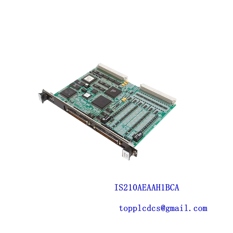
The General Electric 820-0492-01 is a specialized printed circuit board engineered for industrial energy management and power automation infrastructure. Operating as part of GE Energy Services electronic assemblies, this module facilitates critical data processing, monitoring, and signal regulation within complex industrial or utility control environments.
📊 Technical Specifications
- Brand: GE (General Electric / GE Energy Services)
- Model / MPN: 820-0492-01
- Series: Energy Services Control and Processing Series
- Product Name: Energy Printed Circuit Board (PCB)
- Manufacturing Status: Mature / Legacy Industrial Spare Part
- Dimensions: Standard modular subrack / chassis PCB profile
- Weight: Approx. 0.3 kg to 0.6 kg
- Country of Origin: USA / Global Manufacturing Standards
- Power Requirements: Powered internally via system backplane or rack power rails
- Communication: Multi-pin terminal headers and onboard bus connectors
🛠️ Operation Guidelines & Installation
Installation and replacement must be performed strictly by qualified industrial automation technicians or certified electrical engineers. Always ensure that system control power and auxiliary voltage feeds are completely locked out and de-energized before handling the PCB to guard against electrostatic discharge (ESD) and electrical shock hazards. Wear an anti-static grounding wrist strap while inserting the board into its designated chassis slot, ensuring proper alignment with backplane connectors and securing all fastening hardware.
🔌 Power-Up and Power-Down Sequence
Verify that all internal wiring harnesses, backplane pins, and peripheral connections are securely fastened and aligned prior to system startup. Apply system control power to initialize the board’s internal processing architecture and diagnostic routines. Observe onboard status LED indicators to confirm normal operational status. For shutdown or maintenance, back up necessary parameters and safely cut off control power feeds before extracting the board.
📝 Product Usage Instructions
This PCB functions within larger automation racks to monitor and regulate power system data parameters. Keep the control cabinet environment clean, dry, and thermally regulated to prevent premature component degradation from dust, moisture, or chemical vapor exposure. Regularly inspect connector pins and solder joints for signs of thermal stress or mechanical wear.
❓ Common Questions (Q&A)
Q: What should I do if the PCB fails to initialize or shows fault indicators?
A: First, check that the board is firmly seated in its backplane slot and that input power rails are stable. Second, review system-level diagnostic software logs to trace error codes related to this module.
Q: Can this board be hot-swapped while the system is powered on?
A: Live replacement is typically discouraged unless explicitly supported by your specific system’s hardware redundancy and maintenance documentation.
Q: Does this circuit board require programmable software configuration?
A: Configuration parameters are typically handled via system-level controllers or firmware routines tied to the specific industrial enclosure housing the board.
🚀 Recommended Related Models
- GE 820-0511-01 (Power System Board)
- GE 820-0480-01 (Wesdac Main Circuit Board)
- GE 820-0414 (Digital Output Module)
- GE 820-0418 (Analog Input Module)
- GE 820-0419 (Digital Input Module)
- GE Multilin SR750 Feeder Management Relay
- GE Multilin D60 Line Distance Protection System
- GE D400 Substation Gateway Controller
- GE EnerVista Communication Hub Gateway
- GE Substation Communication Interface Card