
Description
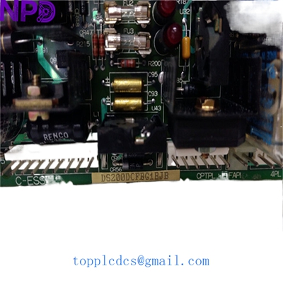
- Model: DS200DCFBG1BJB
- Brand: General Electric (GE)
- Series: Speedtronic Mark V / DC2000 Drive Series
- Core Function: DC Power Supply, Motor Feedback, and I/O Control Board
- Product Type: Power Supply and Feedback Interface Board
- Key Specs: 125V DC Logic | SCR Gate Triggering | Integrated Feedback Circuitry
- Logic Input Voltage: 125 V DC (nominal)
- Control Architecture: Designed for GE Speedtronic Mark V Gas/Steam Turbine Control
- On-board Functions:
- AC-to-DC rectification for internal logic power
- Motor field current feedback monitoring
- Armature voltage/current feedback
- Gate pulse distribution for SCR bridges
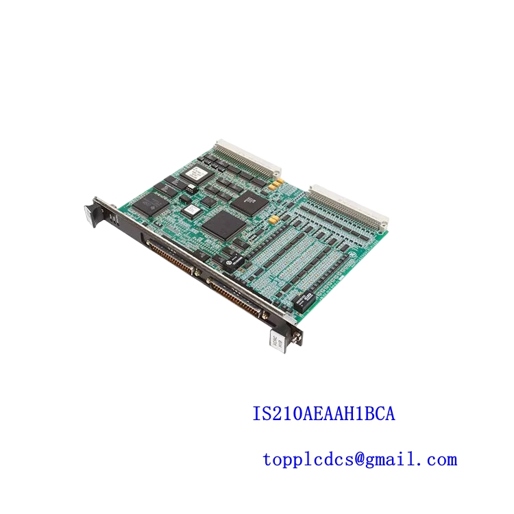
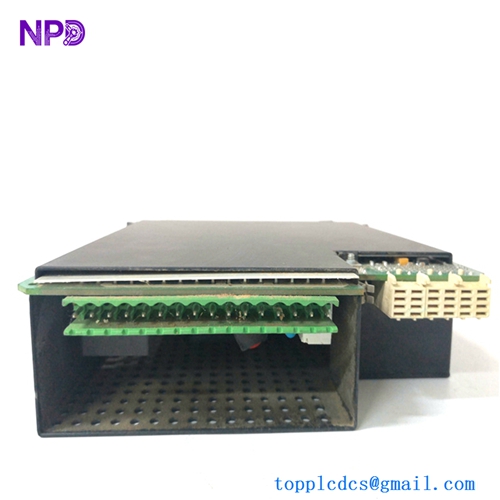
- I/O Interface: High-density ribbon cable headers (60-pin and 34-pin)
- Fusing: Multiple on-board fast-acting fuses for circuit protection
- Diagnostic Indicators: 5-7 Status LEDs (Power, Run, Fault, and Communication)
- Revision Level: G1BJB (Includes specific firmware/component hardware updates)
- Dimensions: Approx. 11.5 x 8.5 inches (Standard GE large-frame PCB)
GE DS200DCFBG1BJB
Installation & Configuration Guide
Stage 1: Pre-Installation
⚠️ Safety Warning:
- Lethal DC Voltage: This board handles 125V DC logic and is physically adjacent to high-voltage SCR bridges. Ensure all upstream breakers are locked out.
- Discharge Time: Wait at least 15 minutes for bus capacitors to bleed down. Measure the DC bus with a 1,000V rated multimeter before proceeding.
- ESD Sensitivity: The DS200DCFBG1BJB contains sensitive CMOS logic. A grounded anti-static wrist strap is mandatory during handling.
Required Tools:
- 1/4″ Nut driver (for mounting standoffs)
- Needle-nose pliers (for jumper adjustments)
- Digital Multimeter (e.g., Fluke 87V)
- Labeling tape for cable identification
Stage 2: Removal
Steps:
- Map the Ribbon Cables: This board has several identical ribbon connectors (e.g., 6PL, 1PL). Label each one carefully; reversing these can lead to “Processor Fault” or hardware damage.
- Disconnect Power: Remove the screw-down power terminals. Check the wires for signs of overheating or frayed insulation.
- Unmount the PCB: Remove the mounting screws. Pay attention to the nylon spacers—these prevent the back of the board from shorting against the metal frame.
Stage 3: Installation
Steps:
- Jumper Mirroring (Critical):
- Locate the jumpers (e.g., JP1, JP2, JP3) on the old board.
- These jumpers configure the voltage scaling and feedback ratios.
- Ensure the jumpers on the new DS200DCFBG1BJB are in the exact same positions as the unit being replaced.
- Mounting: Secure the board to the standoffs. Tighten screws to a firm “snug” fit—do not over-torque, as this can cause hairline cracks in the PCB traces.
- Cable Reconnection: Seat the ribbon cables firmly. You should feel a slight “click” as the locking ears engage.
Stage 4: Power-On & Testing
Validation:
- Static Voltage Check: Apply control power only. Verify the 125V DC input at the terminal block is within ±10%.
- LED Status:
- The “Power OK” LED should be steady.
- Watch for the “Heartbeat” or “Active” LED which indicates communication with the main Mark V controller.
- Drive Calibration: In my experience, even with identical jumper settings, you may need to perform a “Software Autotune” or “Zero-Calibration” via the Mark V operator interface to account for slight component tolerances in the feedback circuitry.
GE DS200DCFBG1BJB
Customer Cases & Industry Applications
Case 1: Gas Turbine Control System Restoration
Situation: A power plant in Southeast Asia experienced a sudden “DC Feedback Failure” trip on their GE Mark V controlled turbine. The DS200DCFBG1BJB board had a visible burn mark near the logic power rectifier.
Task: The plant was losing $15,000 in revenue for every hour the turbine was offline. The OEM lead time was quoted at 8-10 months for a legacy component.
Action: We supplied a New Surplus DS200DCFBG1BJB from our stock. We provided high-resolution photos of the board’s serial number and factory test seal to the client before they finalized the purchase.
Result: The board was shipped via DHL Express and arrived within 3 days. After mirroring the jumpers, the turbine was synced back to the grid within 4 hours of the part arriving on-site.
Case 2: Steel Mill Drive Maintenance
Situation: A major steel mill uses GE DC2000 drives for their rolling line. They noticed that the armature voltage feedback on one drive was becoming noisy, leading to speed fluctuations.
Task: Prevent a catastrophic breakdown during the peak production season by replacing the aging feedback interface board.
Action: The mill purchased two DS200DCFBG1BJB units—one for immediate replacement and one for strategic inventory.
Result: The replacement solved the noise issue immediately. By sourcing New Surplus rather than “Refurbished,” the mill ensured they had the maximum possible MTBF (Mean Time Between Failures) for their legacy system.
Frequently Asked Questions (FAQ)
Q: Is the “BJB” revision compatible with my “BJA” board? A: Generally, yes. The “BJB” revision is a later version of the “G1” series and is designed to be backward compatible. However, it is vital to verify that the firmware EPROMs (if present) are either compatible or swapped from the original board if they contain site-specific configurations.
Q: Do you sell refurbished versions of this board? A: No. Honestly, refurbished DCFB boards are risky. They often have aged electrolytic capacitors that can fail shortly after being re-energized. We only deal in New Surplus units—original GE parts that have never been installed.
Q: Does this board come with the fuses pre-installed? A: Yes, our New Surplus DS200DCFBG1BJB boards come with the standard factory-installed fuses. We recommend verifying their continuity with a multimeter before installation just to be safe.
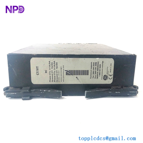
Q: How do I identify the revision of my current board? A: Look for the text printed on the side or the corner of the PCB. It should clearly state DS200DCFBG1… followed by the revision code. The barcode sticker will also have this information.
Featured Inventory List (Current Stock)
- ABB PM866 Controller
- Bently Nevada 3500/22M Monitor
- TRICONEX 3503E Digital Input
- GE IS215UCVEH2AE Processor
- Honeywell CC-PAIH01 Analog Input
- Siemens 6ES7 414-2XG03-0AB0
- Allen-Bradley 1756-L73
- Schneider 140CPU65150
For more details on these parts, visit our catalog at newplcdcs.