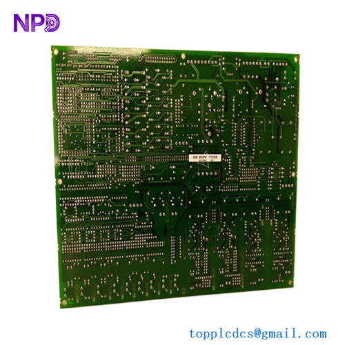

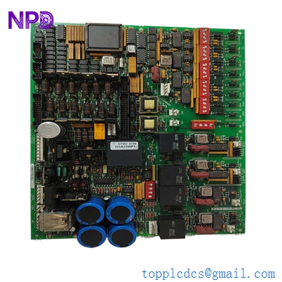
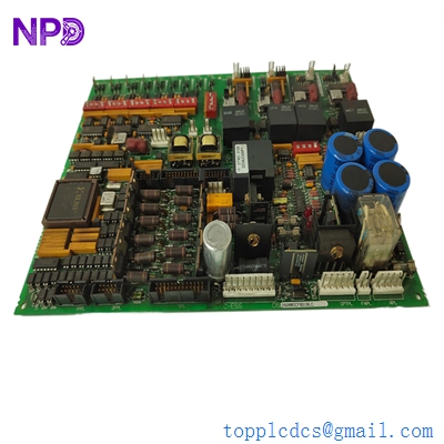
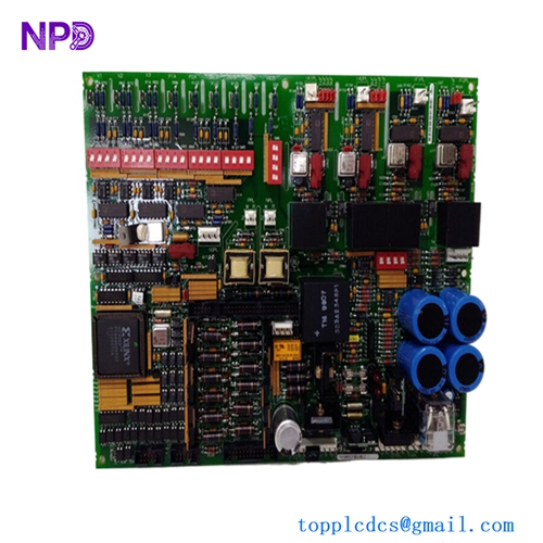
Description
- Model: GE DS200DCFBG1BLC
- Brand: General Electric (GE)
- Series: Mark V / Direct-Connect Drive Series
- Core Function: Provides power distribution, motor feedback, and SCR gate drive signals.
- Product Type: Drive Control Feedback Board (DCFB)
- Key Specs: 125 V DC Nominal Supports 6/12 pulse SCR bridges Multi-tap Transformer inputs
GE DS200DCFBG1BLC
Key Technical Specifications
- Nominal Control Voltage: 125 V DC (Control Power)
- Input AC Range: 38 V AC to 115 V AC (via PTs/Transformers)
- Feedback Loops: Armature Voltage, Field Current, and Tachometer Feedback
- Gate Drive Outputs: 6-pulse SCR firing circuits (expandable)
- Fusing: 3 onboard high-speed fuses for circuit protection
- Connectors: High-density ribbon cable headers for LAN communication
- Isolation: Optical isolation between control logic and power stage
- Diagnostic Indicators: Onboard LEDs for power status and fault detection
- Jumper Configuration: Manual jumpers for scaling and feedback selection
GE DS200DCFBG1BLC
Application Scenarios & Engineering Insights
The DS200DCFBG1BLC is essentially the “Central Nervous System” for GE’s large industrial DC drives and Mark V turbine control systems. In my experience, this board is the most critical link in the feedback loop; it’s responsible for monitoring exactly what the motor is doing and telling the SCRs (Silicon Controlled Rectifiers) how to react. If this board drifts or fails, your motor speed will hunt, or worse, you’ll trip on an overcurrent fault that’s notoriously hard to pin down.
Typical Application Scenarios:
- Gas & Steam Turbine Control (Mark V) Used within the drive lineup to manage fuel pump motors or starter motors, ensuring precise speed regulation during startup sequences.
- Heavy Industrial DC Drives Found in steel mills and paper plants where high-torque DC motors require stable armature and field control.
- SCR Bridge Management Provides the firing pulses needed to turn on large power thyristors in a synchronized 6-pulse or 12-pulse configuration.
Case Study: The “Ghost Trip” at a Steel Cold Mill
Background: A major steel manufacturer was experiencing random “Instantaneous Overcurrent” trips on their main stand drive. It happened three times in one week, each time ruining a coil of steel and costing roughly $12,000 in lost material alone.
The Problem: The site team replaced the SCRs and the main processor, but the trips continued. When we looked at the waveforms, we noticed the gate pulses from the existing DS200DCFBG1BLC were jittering. A small capacitor on the feedback circuit had aged and was causing signal noise.
The Solution: We pulled a DS200DCFBG1BLC from our tested inventory. Before shipping, we verified the jumper settings matched the client’s original “BLC” revision.
The Result: * Recovery: The drive was back online 24 hours after the board arrived.
- Stability: The jitter vanished, and the drive has been running for 14 months without a single “ghost trip.”
- Conclusion: In aging systems like the Mark V, replacing a suspect feedback board is often cheaper than one hour of downtime.
Compatible Replacement Models
The “BLC” suffix in DS200DCFBG1BLC is vital. It denotes specific hardware revisions and functional groups.
| Model | Compatibility | Key Differences | Action Required |
| DS200DCFBG1AAA | ❌ Incompatible | Initial revision; lacks later protection circuits | Not recommended for BLC systems |
| DS200DCFBG1B | ⚠️ Partial | Base version without the “LC” specific options | Check jumper J1-J10 carefully |
| DS200DCFBG2BLC | ⚠️ Software Comp. | Group 2 boards have different voltage ratings | Verify PT ratios in drive parameters |
Engineer’s Note: If you cannot find the exact “BLC” version, some “B” revisions can be modified by moving jumpers, but honestly, it’s a headache. Stick to the exact match whenever possible to avoid recalibrating the entire feedback loop.
GE DS200DCFBG1BLC
Troubleshooting Quick Reference
| Symptom | Possible Cause | Part Relevance | Quick Check |
| Drive Won’t Start; No Fault | Missing 125V DC control power | ❌ Low | Check fuses FU1, FU2, FU3 on the board |
| Armature Overvoltage Trip | Feedback scaling jumper wrong | ✅ High | Compare Jumper JP1/JP2 to old board |
| SCR Mis-firing (Noise) | Ribbon cable interference | ⚠️ Medium | Ensure ribbon cables are away from power bus |
| F1 Fault on Drive | Faulty Pulse Transformer | ✅ High | Measure resistance of gate-cathode leads |
| Unstable Speed | Tachometer feedback drift | ✅ High | Check JP10 for proper tach/encoder select |
❗ Pro-Tip: The Jumper Trap
I’ve seen it a hundred times: an engineer swaps the board, the drive powers up, but as soon as it tries to spin, it trips. 90% of the time, they forgot to move the jumpers from the old board to the new one. GE shipped these boards with “factory default” jumper settings that rarely match your specific motor’s voltage or tachometer type.
- Take a photo of the old board before removing any wires.
- Physically count the jumpers.
- Use a pair of needle-nose pliers to move them one by one.