
Description
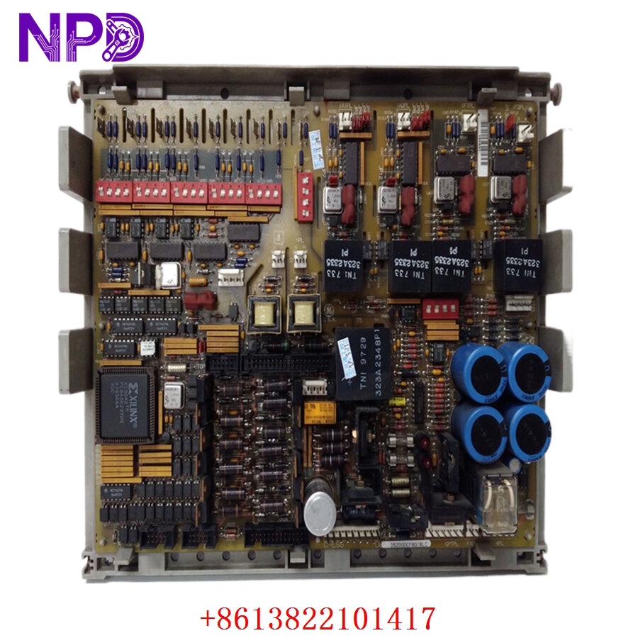
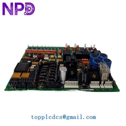
The GE DS200DCFBG1BLC is a sophisticated power supply and control board designed for the Mark V LM or Mark V Speedtronic drive control systems. This DS200DCFBG1BLC board serves as the primary interface for DC feedback and power distribution within the drive, regulating the necessary internal voltages while monitoring critical performance metrics. It is engineered to provide precise regulation of the bridge control and feedback signals, ensuring that high-power industrial drives operate with maximum efficiency and safety in environments such as power generation and heavy manufacturing.
Technical Specifications
- Model Number: DS200DCFBG1BLC
- Series: Mark V / Speedtronic
- Board Type: DC Power Supply and Feedback (DCFB)
- Input Voltage: 125V DC (nominal) or 115V AC (depending on configuration)
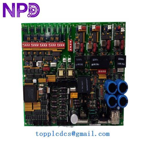
- Outputs: Multiple regulated DC control voltages (+/-15V, +5V, +24V)
- Feedback Loops: Voltage and current feedback for drive bridge control
- Fusing: On-board replaceable fuses for circuit protection
- Connectors: Plug-in terminal blocks and ribbon cable headers
- Revision Level: G1 (Group 1) with BLC modification code
- Protection: Integrated surge suppression and noise filtering This board acts as the central hub for the drive’s control power, integrating comprehensive diagnostic test points that allow technicians to measure voltage levels and signal integrity directly on the hardware during operation.
GE DS200DCFBG1BLC
GE DS200DCFBG1BLC
GE DS200DCFBG1BLC
Model Comparison
The GE DS200DCFBG1BLC is distinguished from the standard DS200DCFBG1A by the “BLC” suffix, which indicates a specific set of factory-installed functional revisions or “artwork” changes designed for specialized drive applications. While all DCFB boards provide power distribution, the G1BLC version often features enhanced feedback sensitivity or specific resistor configurations compared to the earlier G0 series. Unlike the DS200SDCC drive control card, which handles digital processing, the DCFB is primarily focused on the analog power and feedback interface layer.
Operational Tips
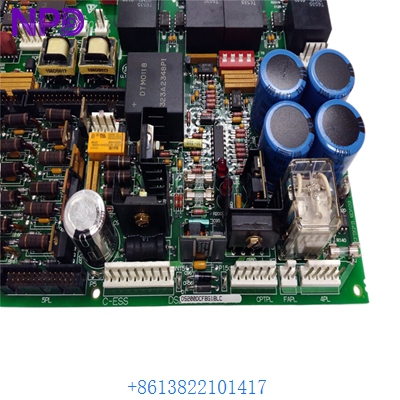
- Fuse Verification: Always check the status of the on-board fuses (e.g., FU1, FU2) if the drive fails to initialize; these are the first line of defense against external power surges.
- Jumper Settings: When replacing an existing board, carefully replicate the positions of all jumpers (JP) from the old board to the new one, as these define the voltage scaling and feedback sources.
- Discharge Time: After powering down the drive, wait at least 10 minutes before touching the DS200DCFBG1BLC to allow high-voltage capacitors to discharge to safe levels.
- Cleaning and Airflow: Ensure the board is free from conductive dust or oil mist; use only dry, low-pressure air for cleaning to prevent short circuits between the high-density traces.