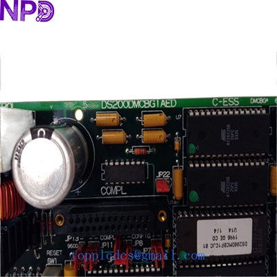

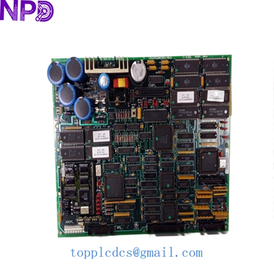
Description
Model: GE DS200DMCBG1AED (Compatible with DS215DMCBG1AZZ03A & DS200DMCBG1AKG) · Brand: General Electric (GE) · Series: Mark V / Mark VI / Innovation Series Drives · Core Function: Drive Memory and Communication Board (DMCB) · Condition: Brand New Surplus (Original New), non-refurbished · Type: Memory & Logic Interface Board · Key Specs: Non-volatile memory storage High-speed bus interface EPROM socketed logic
- Manufacturer: General Electric (GE)
- Part Numbers: DS200DMCBG1AED / DS200DMCBG1AKG
- System Version: DS215 (Later revision architecture)
- Board Category: Drive Memory & Communication (DMCB)
- Storage: Onboard EEPROM and socketed EPROM chips
- Communication: LAN / Drive Control Bus Interface
- Compatibility: GE Innovation Series Drives & EX2000 Excitation Systems
- Operating Voltage: +5 V DC / +/- 15 V DC (Via Backplane)
- Configuration: Jumper-selectable address and parity settings
- Operating Temp: 0°C to +55°C (32°F to 131°F)
GE DS215DMCBG1AZZ03A DS200DMCBG1AED DS200DMCBG1AKG
Installation & Configuration Guide
Phase 1: Pre-Installation (Preparation)
⚠️ Safety Protocol:
- Notify production of the scheduled control system outage.
- Completely de-energize the drive cabinet. Verify zero voltage on the system bus.
- Establish a static-controlled environment. The DMCB series utilizes high-density CMOS memory chips that are extremely vulnerable to ESD (Electrostatic Discharge).
Tools Required:
- Anti-static wrist strap and mat.
- IC extractor tool (if moving firmware chips).
- Fine-tip needle-nose pliers for jumpers.
Phase 2: Removing the Faulty Module
- Firmware Audit: Check if your old board has socketed chips with white stickers (e.g., U6, U7). These contain the site-specific drive parameters and firmware.
- Connector Check: Carefully unplug any local ribbon cables. Note the orientation of Pin 1 (usually the red stripe).
- Removal: Release the locking tabs and slide the board out of the rack. To be honest, these legacy racks can be tight; pull straight and steady to avoid flexing the PCB.
Phase 3: Hardware Configuration
- Jumper Mirroring: Compare the jumpers (JP1, JP2, etc.) on the new DS200DMCBG1AED with your old board. These jumpers define the memory addressing and communication protocols.
- Chip Swap (Critical): If your new board is “blank,” you must move the EPROM chips from the old board to the new one. Ensure the notch on the chip aligns with the notch on the socket. If you put them in backward, you will fry the firmware upon power-up.
- Seating: Slide the new board into the rack guides until the backplane connectors seat firmly.
Phase 4: System Re-Commissioning
- Initial Power: Apply control power only.
- Diagnostic LEDs: Watch the status LEDs. A healthy DMCB board should initialize and pass the self-test, typically indicated by a specific blink pattern or solid green light.
- Parameter Verification: Access the drive’s diagnostic menu via the keypad or GE toolbox software. Verify that the drive recognizes the memory board and that the checksums match.
- Test Run: Perform a “No-Load” test run to ensure communication between the DMCB and the main control processor is stable.
Customer Cases & Industry Applications
Case 1: Paper Mill Controller Failure
A large paper mill in the Pacific Northwest experienced a “Memory Checksum Error” on their main winder drive. The DS200DMCBG1AED board had failed due to a localized power surge. The OEM lead time was non-existent as the part is obsolete. We supplied a New Surplus board with the “AKG” revision level. The mill’s electrical lead swapped the firmware chips and had the winder back in production within 4 hours of receiving the part.
Case 2: Gas Turbine Excitation System
A power plant utilizing the GE EX2000 excitation system needed a reliable spare for their DMCB board. They had previously tried a refurbished board from another vendor that failed within three weeks. They turned to us for an “Original New” DS215DMCBG1AZZ03A. Since installing our board in 2024, the system has run without a single communication dropout, proving the ROI of investing in New Surplus over used hardware.
GE DS215DMCBG1AZZ03A DS200DMCBG1AED DS200DMCBG1AKG
Frequently Asked Questions (FAQ)
Q: What is the difference between the DS200 and DS215 versions? A: The DS215 is a later hardware platform. While the core “DMCB” function is the same, the DS215 boards often feature updated components and better noise immunity. In most GE Innovation drives, they are backward compatible, but you should always verify the specific “G1” group number matches.
Q: Does this board come with my drive’s parameters pre-loaded? A: No. Memory boards ship with factory-default logic or are blank. You must either download your backed-up parameters via software or physically move the socketed EPROM chips from your old board to the new one.
Q: Why does my board have an “AED” suffix while the other says “AKG”? A: These are revision codes. “AKG” is generally a later revision than “AED.” GE design ensures that later revisions are backward compatible with earlier ones. We recommend using the latest revision available for better reliability.
Q: Is this board “New Surplus” or “Refurbished”? A: We only deal in New Surplus for the DMCB series. These are original GE parts that have been kept in climate-controlled storage and have zero operating hours.
Related Inventory Models
- GE DS200SDCCG1A (Drive Control Board)
- GE DS200TCQAG1A (Analog I/O Board)
- GE DS200KLDBG1A (Display/Keypad Board)
- ABB PM866
- Bently Nevada 3500/22M
- Triconex 3008
- Honeywell MC-TAMT03
- Siemens 6ES7315-2AH14-0AB0
For real-time availability and volume pricing, please visit newplcdcs www.newplcdcs.com.