
Description
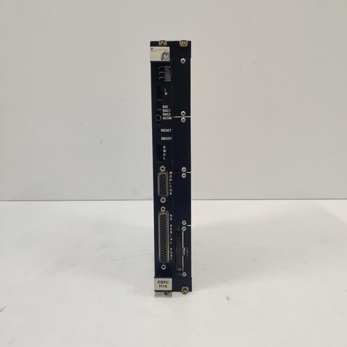
GE DS200DSPCH1AEA / DS200ADMAH1AAC | Digital Signal Processor Control Board
The GE and DS200ADMAH1AAC are high-performance Digital Signal Processor (DSP) boards engineered for General Electric’s industrial drive control systems and Mark V turbine control lines. The DS200DSPC board functions as the primary computational hub, running complex motor control algorithms, processing real-time feedback loop inputs, and generating precision gate firing signals. Working in tandem with specialized daughter cards or interface modules like the DS200ADMA, this hardware configuration ensures exceptional operational stability, tight torque regulation, and rapid diagnostic fault monitoring for heavy-duty industrial applications.
Product Datasheet
- Model Identification: DS200DSPCH1AEA / DS200ADMAH1AAC
- Product Series: Mark V Speedtronic / Innovation Series Drive Control
- Manufacturer: General Electric (GE)
- Country of Origin: United States (USA)
- Dimensions: Approximately 295 mm x 112 mm x 25 mm (11.6 in x 4.4 in x 0.98 in)
- Weight: Approximately 0.65 kg (1.43 lbs) per individual board assembly
- Processor Type: Dual 32-bit digital signal processors with high-speed mathematical calculation logic
- Onboard Interfaces: Front-facing configuration port, diagnostic serial interface, high-density ribbon cable headers, and plug-in modular board connectors
Target Applications
This digital signal processing architecture is widely deployed across critical power and automation sectors:
- Gas and Steam Turbine Control: Part of the Mark V Speedtronic matrix for calculating fuel-to-air ratios, valve positions, and overspeed trip logic.
- Heavy-Duty Industrial Drives: Used in high-horsepower AC and DC drive systems that power rolling mills, mining hoists, and heavy manufacturing equipment.
- Renewable Energy Plants: Integrated into large-scale power inverter control networks for wind turbine generators and grid-synchronization gear.
- Oil and Petrochemical Systems: Deployed in continuous-process compression trains requiring synchronized multi-axis control loops.
Operating Instructions
To preserve hardware integrity and achieve optimal system performance, adhere to the following setup parameters:
- Electrostatic Safeguards: Both modules contain highly sensitive integrated circuits. Always wear a grounded ESD wrist strap and handle the boards strictly by their outer edges or plastic brackets during installation.
- Interboard Connections: Securely mate the DS200ADMA interface card to the dedicated multi-pin connector sockets on the host DS200DSPC mother board. Ensure all mounting standoffs are locked down to avoid misalignment under thermal expansion.
- System Power Sequence: Verify that the primary control rack power supply is completely switched off before inserting or removing the DSP board assembly. Hot-swapping these modules can damage memory components and interrupt system networks.
- Firmware Verification: Ensure that any modular EEPROM chips or configurable jumpers transferred from an old board match the layout requirements of the replacement hardware revision before power-up.
Common Questions & Answers
What are the primary differences between the DS200DSPC and DS200ADMA components? The DS200DSPC acts as the core calculation unit containing the main processing chips and programming logic. The DS200ADMA serves as an auxiliary adapter or interface board that extends the system’s specialized I/O capacity and signal routing pathways.
How do the revision letters at the end of the part numbers affect compatibility? The trailing characters “H1AEA” and “H1AAC” indicate specific functional revisions, software base levels, and hardware updates. When executing a replacement, matching these exact revision strings ensures plug-and-play compatibility without necessitating broader system upgrades.
What is the meaning of the status indicators on the front plate assembly? The array of front-panel LEDs provides localized troubleshooting telemetry. A solid green light typically indicates stable processor power and a successful boot sequence, while blinking red or amber sequences point toward specific communication loss or calculation faults.
Are there specialized cooling prerequisites for this DSP cluster? The boards are engineered for convective cooling within standard industrial cabinets. It is essential to keep the rack filter elements clean and ensure that ambient enclosure temperatures do not exceed the specified industrial limits to prevent thermal throttling.