
Description
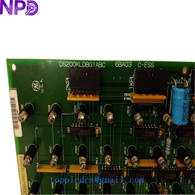
Model: GE DS200KLDBG1ABC (Cross-ref: DS215KLDBG1AZZ03A) · Brand: General Electric (GE) · Series: Mark V / Mark VI / Innovation Series Drives · Core Function: Local operator interface and diagnostic display board · Condition: Brand New Surplus (Original New), non-refurbished · Type: Display and Keypad Interface Board (KLDB) · Key Specs: 16-character LCD Tactile Keypad Direct ribbon connector interface
- Manufacturer: General Electric (GE)
- Part Number: DS200KLDBG1ABC
- Alternate Number: DS215KLDBG1AZZ03A
- Display Type: Liquid Crystal Display (LCD)
- Configuration: 2 lines x 16 characters
- Input Interface: 16-key tactile membrane keypad
- Power Requirement: +5 V DC (Supplied via control bus)
- Connection: 10-pin or 16-pin ribbon cable (Model dependent)
- Operating Temp: 0°C to +55°C (32°F to 131°F)
- Humidity: 5% to 95% Non-condensing
- Mounting: Front panel mount with integrated standoffs
GE DS200KLDBG1ABC DS215KLDBG1AZZ03A
Installation & Configuration Guide
Phase 1: Pre-Installation (Preparation)
⚠️ Safety Protocol:
- Notify production of the scheduled downtime.
- Ensure all AC power to the drive or turbine control cabinet is disconnected and tagged out.
- Wait for the internal capacitors to discharge (approx. 10 minutes).
- Use a grounded anti-static wrist strap. The DS200KLDBG1ABC contains sensitive logic chips that can be damaged by static electricity.
Documentation:
- Take a photo of the ribbon cable orientation on the old board. The “Red Stripe” usually indicates Pin 1, but it’s best to verify before removal.
Phase 2: Removing the Old Display Board
- Access: Open the front cabinet door. The KLDB board is usually mounted directly behind the operator faceplate.
- Disconnecting: Gently unplug the ribbon cable. These connectors can become brittle over time—pull by the plastic housing, not the cable.
- Unmounting: Loosen the mounting nuts or screws holding the board to the panel. Keep these in a safe place as replacements are often hard to find.
Phase 3: Installing the New Module
- Jumper Check: Verify if there are any hardware jumpers (e.g., J1, J2) on the back of the board. In my experience, these are rarely changed, but they should match the old unit.
- Mounting: Align the new DS200KLDBG1ABC with the front panel window. Tighten the mounting hardware to about 0.3 N·m.
- Cabling: Reconnect the ribbon cable. Ensure the connector is fully seated and the locking tabs click into place.
Phase 4: Power-On & Testing
- Initial Power: Apply control power. The LCD should initialize and display the firmware version or a “Ready” status.
- Keypad Test: Press the “Menu” or “Status” keys to ensure the tactile buttons are registering inputs.
- Contrast: If the text is hard to read, look for a small potentiometer (R1) on the back of the board to adjust the LCD contrast.
- Final Check: Ensure the board communicates with the main processor by verifying that live data (Current, Voltage, or Speed) is updating on the screen.
Customer Cases & Industry Applications
Case 1: Gas Turbine Control Emergency
A power plant in the Middle East had a “Display Failure” on their Mark V turbine control panel. The operator could not see critical alarms or clear faults locally. The OEM suggested a full panel upgrade costing over $100,000. By sourcing a New Surplus DS215KLDBG1AZZ03A from our inventory, the plant restored local control in less than 24 hours. The maintenance manager noted that the cost of our board was less than the lost revenue from just 15 minutes of downtime.
Case 2: Steel Mill Drive Maintenance
A steel rolling mill in Pennsylvania used legacy GE Innovation Series drives. The keypad on the DS200KLDBG1ABC had become unresponsive due to years of oil and dust exposure. The mill purchased two units—one for immediate replacement and one for strategic stock. This proactive move saved them from an unplanned stoppage when a second drive’s display failed during a high-output production run six months later.
Frequently Asked Questions (FAQ)
Q: Are DS200KLDBG1ABC and DS215KLDBG1AZZ03A interchangeable? A: Yes. The “DS215” prefix often indicates a later manufacturing revision or a version used in newer Mark VI systems, but for the KLDB (Keypad Display Board) function, they are functionally identical and backward compatible.
Q: Do I need to load software onto this board? A: No. This is a “dumb” interface board. It receives data from the main control processor. However, it does contain its own local firmware for managing the LCD and keypad logic, which is pre-installed at the factory.
Q: The screen is blank after I installed it. What’s wrong? A: First, check the ribbon cable orientation. If it is flipped, the board won’t get power. Second, check the contrast adjustment screw (usually labeled R1). Sometimes the contrast is set too low for certain lighting conditions.
Q: Is this board “New Surplus” or “Refurbished”? A: We only sell New Surplus units for this model. These are authentic GE parts that have never been used in the field. Given the critical nature of Mark V/VI systems, we do not recommend using refurbished display boards.
GE DS200KLDBG1ABC DS215KLDBG1AZZ03A
Related Inventory Models
- GE DS200SDCCG1A (Drive Control Board)
- GE DS200TCQAG1A (Analog IO Board)
- GE IS200EPBPG1A (Power Backplane)
- ABB PM866
- Bently Nevada 3500/22M
- Triconex 3008
- Honeywell MC-TAMT03
- Siemens 6ES7315-2AH14-0AB0
For current pricing and a formal quote, please visit newplcdcs www.newplcdcs.com.