Description
- Model: GE DS200TBQCG1AAA
- Brand: General Electric (GE)
- Series: Mark V Speedtronic Control System
- Core Function: Relay output termination and signal conditioning
- Product Type: Terminal Board (TBQC)
- Key Specs: 12 Relay Outputs Fused Protection Screw Terminal Blocks
- Relay Count: 12 plug-in magnetic relays
- Contact Ratings: Typically 120 V AC or 24 V DC (application dependent)
- Fusing: Individual glass tube fuses for output protection
- Terminations: Dual-row barrier-style screw terminal blocks
- Connectors: Two 50-pin ribbon cable headers (J1 and J2) for I/O core interface
- Mounting: Standard Mark V R, S, or T core DIN rail/standoff mounting
- Diagnostic LEDs: Visual indication for relay coil energization
- Signal Types: Solenoid drivers, alarm contacts, and interposing logic
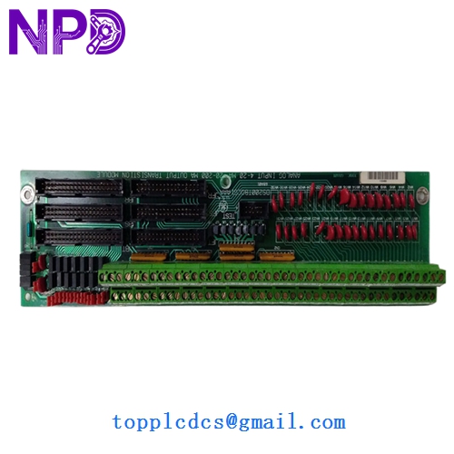
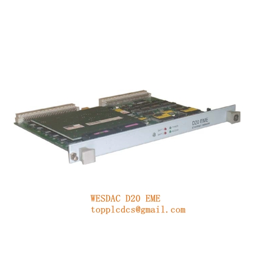
GE DS200TBQCG1AAA
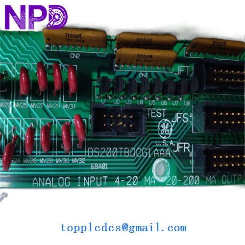
GE DS200TBQCG1AAA
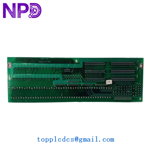
GE DS200TBQCG1AAA
Application Scenarios & Pain Points
In the GE Mark V “TMR” (Triple Modular Redundant) architecture, the DS200TBQCG1AAA acts as the final physical interface for relay-based commands. It’s the board that actually “clicks” to open a fuel valve or start a lube oil pump. Because it sits at the edge of the system, it is frequently exposed to field-side electrical surges. If a solenoid shorts out, it can take a trace on this board with it.
Typical Application Scenarios:
- Turbine Fuel Control Managing the trip solenoids and fuel skid valves where high-reliability switching is mandatory.
- Auxiliary Motor Starting Interfacing the low-power PLC logic with the motor starters for pumps and fans.
- Emergency Trip Systems Part of the “protective” layer of the Mark V core, ensuring the machine safely shuts down during a fault.
- Plant Alarms & Annunciation Driving physical sirens or lamps in the control room based on DCS logic.
Case Study: The “Sticky” Solenoid Mystery
: A combined-cycle power plant in Southeast Asia was experiencing random “Fuel Valve Fail to Close” alarms. The software showed the command was sent, but the valve didn’t move.
: The maintenance team initially replaced the valve solenoid, but the problem returned two days later. Upon inspection of the DS200TBQCG1AAA board, I noticed carbon tracking around one of the relay sockets. The relay contacts were intermittently welding together due to inductive kickback from an aging solenoid.
: We replaced the TBQC board with a fresh DS200TBQCG1AAA from stock and added external snubbers to the field wiring to prevent future arcing.
: – System Stability: Alarms cleared immediately.
- Reliability: The unit has now run for 18 months without a repeat failure.
- Engineer’s Note: “Always check the fuses and relay sockets on these boards first; they are the most common failure points in high-cycle applications.”
Compatible Replacement Models
The TBQC board is relatively straightforward, but the “AAA” suffix is critical for physical dimensions and fuse ratings.
| Model | Compatibility | Note |
|---|---|---|
| DS200TBQCG1AAA | Direct Replacement | The standard baseline model. |
| DS215TBQCG1A | ⚠️ Software Compatible | Later version with updated components; usually fits but verify mounting holes. |
| DS200TBQCB1A | ❌ Incompatible | Different relay configuration; do not swap. |
Troubleshooting Quick Reference
| Symptom | Possible Cause | Relation | Quick Check |
|---|---|---|---|
| Command sent, relay doesn’t click | Blown Fuse | ✅ High | Check the glass fuse associated with that specific output. |
| Relay clicks, but no field voltage | Contact Wear | ✅ High | Measure resistance across terminal screws when energized. |
| All relays on board inactive | Ribbon Cable Issue | ⚠️ Med | Inspect 50-pin J1/J2 cables for seated connection or corrosion. |
| LED is on, but device won’t start | Field Wiring | ❌ Low | Measure voltage at the terminal block (TB1/TB2). |
❗ Technical Warning: The “Hot Swap” Myth
While some modern DCS modules claim hot-swap capability, do not pull the ribbon cables (J1/J2) on a DS200TBQCG1AAA while the Mark V core is powered. I’ve seen backplane spikes trip the entire turbine because the “R” core lost its I/O heartbeat. Always power down the specific core you are servicing.
Wiring Note:
When replacing this board, label every wire. The screw terminals look identical, and it’s incredibly easy to swap a feedback wire with a 125 V DC command wire. Take a photo of the wiring loom before loosening a single screw. It will save you hours of tracing later.