Description
Product Specifications
- Origin: United States (USA)
- Weight: 2.10 lbs (0.95 kg)
- Dimensions: 11.0 inches x 7.5 inches x 1.5 inches
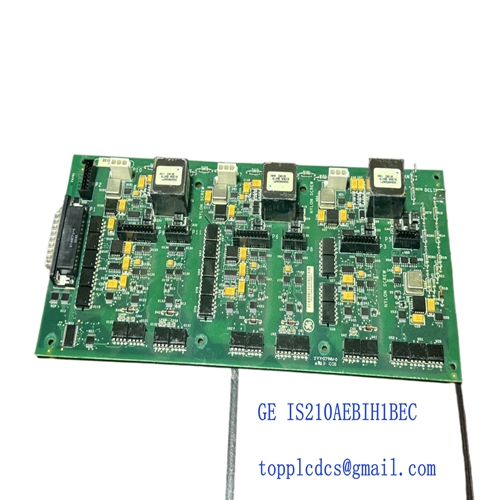
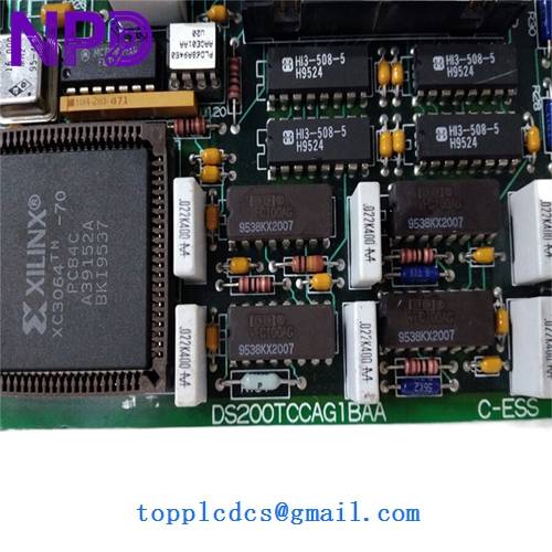
- Board Function: Serves as the primary interface for digital and analog I/O signals within the Mark V Speedtronic turbine control system.
- Processor Architecture: Equipped with high-speed microprocessors capable of executing real-time control algorithms and processing sensor feedback.
- Interface Connectors: Features multiple specialized ribbon cable headers (including J sockets) to communicate with the core processing and distribution modules.
The GE DS200TCCAG1BAA is a critical component of the Mark V turbine control series, acting as the communication bridge between the control processors and the physical field devices. This board is engineered to handle various signal types, including flame detection signals, pulse rates, and analog inputs, converting them into digital data for the system’s core. Its multi-layered design ensures high electromagnetic interference (EMI) resistance, providing stable performance in the harsh electrical environments typical of power generation facilities and industrial plants.
Model Comparison: DS200TCCAG1BAA vs. Similar Models
The DS200TCCAG1BAA is distinguished from other TCCA variants by its specific revision code (“G1BAA”). While the base TCCA architecture is standard across many Mark V systems, the G1BAA version includes specific hardware optimizations and factory-loaded firmware that may not be present in earlier “G1A” or “G1B” iterations. Specifically, the “BAA” suffix often denotes a more modern manufacturing standard with improved surface-mount component reliability and expanded compatibility with later versions of the Mark V software environment.
GE DS200TCCAG1BAA
GE DS200TCCAG1BAA
GE DS200TCCAG1BAA
Operational Guidelines
- Handling Precautions: This assembly is highly susceptible to Electrostatic Discharge (ESD); ensure you are working at an ESD-safe workstation and wearing a grounded wrist strap before touching the board.
- EEPROM Management: When replacing an existing board, ensure that the configuration data and EEPROMs are transferred or reprogrammed to match the specific turbine parameters of your site.
- Slot Alignment: Verify that the board is fully seated in the control rack and that the nylon standoffs are securely fastened to prevent vibration-induced signal loss.
- Cabling Sequence: When reconnecting ribbon cables, follow the designated numbering on the board (e.g., J1, J2) to ensure that I/O signals are routed to the correct processing channels.