Description
- Model: GE DS200TCEBG1ACE
- Brand: General Electric (GE)
- Series: Mark V Speedtronic (TMR Architecture)
- Core Function: Emergency overspeed and protective termination
- Product Type: Protective Engine Termination Board (TCEB)
- Key Specs: Supports <P> core protection Triple Redundant inputs Overspeed pulse sensing
- Protection Interface: Interfaces with the <P> (Protective) core in Mark V systems
- Overspeed Sensing: Processes magnetic pickup (MPU) pulse signals for turbine speed
- Flame Detection: Termination points for flame scanner signals
- Trip Logic: Controls the Emergency Trip Board (TREB) relays
- Redundancy: Triple Modular Redundant (TMR) compatible
- Connectors: High-density 50-pin ribbon headers and screw terminals
- Fusing: Onboard protection for field-side DC power distribution
- Voltage Monitoring: Integrated sensing for bus and battery voltage levels
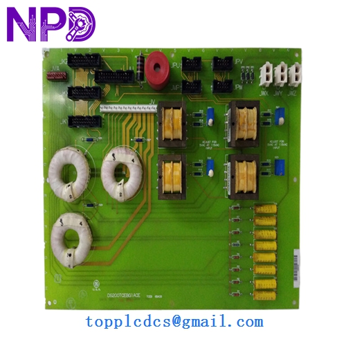
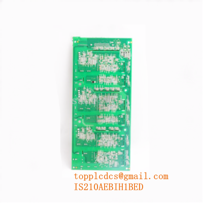
GE DS200TCEBG1ACE
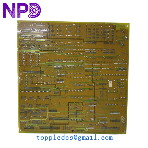
GE DS200TCEBG1ACE
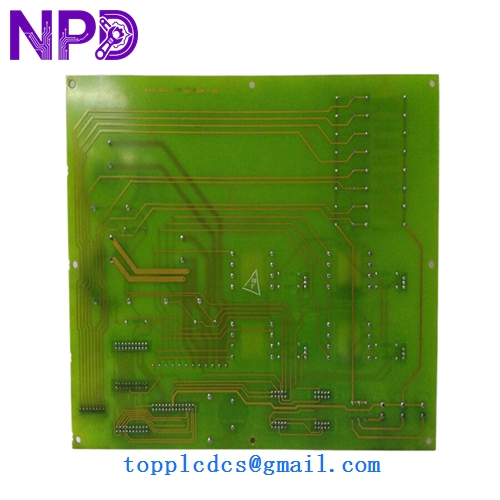
GE DS200TCEBG1ACE
Application Scenarios & Pain Points
In the GE Mark V world, the DS200TCEBG1ACE is part of the final line of defense. This board sits in the “Protective” core—often called the <P> core—and its primary job is to ensure that if the main control cores (<R>, <S>, <T>) fail, the turbine can still be safely tripped during an overspeed event. If this board develops a fault, you aren’t just looking at a control error; you’re looking at a “Protection Loss” alarm that will usually prevent the machine from starting entirely.
Typical Application Scenarios:
- Turbine Overspeed Protection Monitoring magnetic pickups to trigger a hard trip if the shaft speed exceeds safety limits.
- Flame Monitoring & Trip Processing ultraviolet (UV) or intensity-based flame signals to ensure fuel is cut if the fire goes out.
- Emergency Manual Trips Handling the physical hard-wired emergency stop buttons from the local and remote control panels.
- Generator Protective Interfacing Managing signals between the generator protection relays and the turbine control logic.
Case Study: The Ghost Trip at 3,000 RPM
Background: A utility-scale gas turbine in the Pacific Northwest was suffering from “Protection Core Diagnostic” alarms that caused the machine to trip just as it reached synchronous speed.
Problem: The site team suspected the magnetic pickups (MPUs) on the shaft. They replaced all three sensors, but the speed mismatch persisted in the <P> core. Every failed start cost the plant thousands in fuel and emissions “startup” penalties.
Solution: After checking the signals with an oscilloscope, we found that the frequency-to-voltage converter circuit on the DS200TCEBG1ACE had drifted. We supplied a tested “ACE” revision board.
Result: – Successful Start: The turbine synchronized on the first attempt after replacement.
- Precision: Speed readings across all three channels were within 1 RPM of each other.
- Engineer’s Insight: “In the Mark V, the <P> core is its own island. If you have speed discrepancies only in the protective core, look at the TCEB board, not just the sensors.”
Compatible Replacement Models
The “ACE” suffix indicates a specific revision level. While GE boards are generally backward compatible, the protection core is sensitive to hardware revisions.
| Original Model | Replacement Model | Compatibility | Main Difference | Change Required | Cost Impact |
|---|---|---|---|---|---|
| DS200TCEBG1A | DS200TCEBG1ACE | ✅ Direct | ACE is a later, improved revision. | None | Base |
| DS200TCEBG1ACE | DS200TCEBG2ACE | ⚠️ Software | Group 2 boards may have different scaling. | Check software constants. | +15% |
| DS200TCEBG1ACE | DS215TCEB… | ❌ Incompatible | Mark VI version; different architecture. | Entire core upgrade. | N/A |
Technical Tip: Always verify the “Group” (G1 vs G2). G1 is the most common for standard gas turbines, while G2 is often found in specific steam turbine or industrial drive configurations.
Troubleshooting Quick Reference
| Symptom | Possible Cause | Relation | Quick Check | Action |
|---|---|---|---|---|
| “P Core Communication Loss” | Ribbon Cable | ⚠️ Med | Inspect the 50-pin cable to the TCEA board. | Reseat cable; check for bent pins. |
| Incorrect Speed Reading in <P> | TCEB Scaling | ✅ High | Compare <P> core speed vs <R,S,T> cores. | Recalibrate or replace TCEB board. |
| Flame Signal Missing (Board Only) | Input Opto-isolator | ✅ High | Measure mA/V at TCEB screw terminals. | If voltage is present at TB but not in logic, replace board. |
| F1 / F2 Fuse Blown | Field Short | ❌ Low | Check 125V DC solenoid wiring for grounds. | Clear ground fault before replacing board. |
❗ Critical Safety Note: The “Overspeed” Test
Whenever you replace a DS200TCEBG1ACE, you must perform a functional overspeed trip test (either electronic or physical, depending on plant SOP) before returning the unit to commercial service. Since this board handles the trip path, you have to prove it can actually drop the relays before you trust it with a multi-million dollar turbine.
Wiring & Configuration:
Before pulling the old board, check the DIP switches and Jumpers. The TCEB has several hardware settings for speed sensor types (passive vs active) and flame scanner voltage levels. If the new board isn’t “jumpered” to match the old one, you might not see any speed signal at all. Match the jumpers exactly.