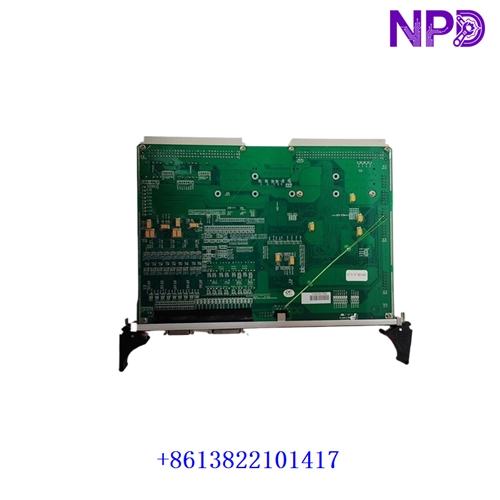
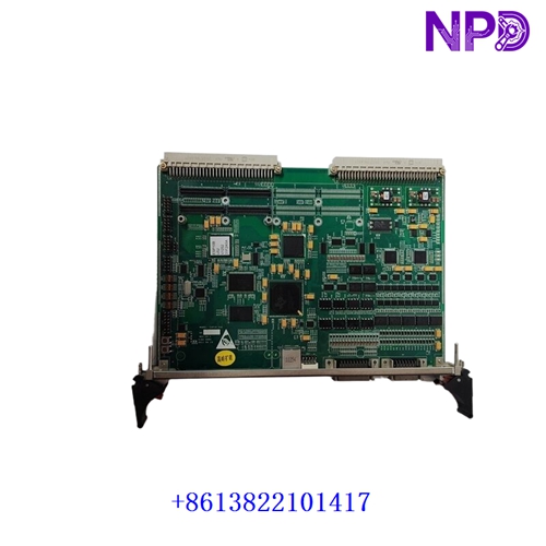
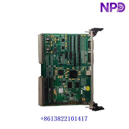

Description
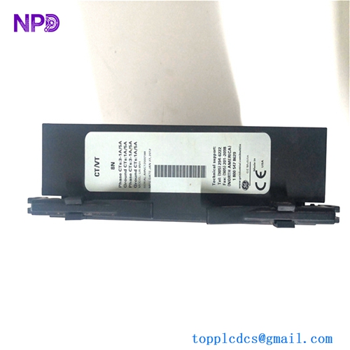
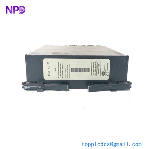
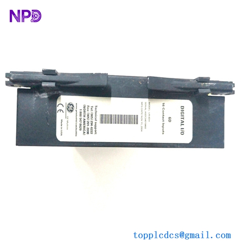
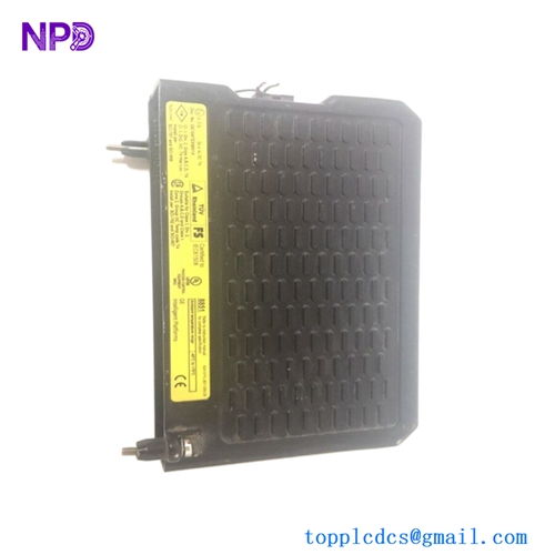
The GE ESP10B is an advanced industrial control and monitoring unit engineered specifically for electrical submersible pump (ESP) systems used in oil and gas extraction, municipal water supply, and heavy industrial fluid management. Designed to operate in demanding subsurface and surface environments, this controller delivers reliable motor management, real-time parameter tracking, and comprehensive protection against electrical anomalies.
Built with robust industrial-grade architecture, the unit ensures optimal motor performance by regulating voltage, frequency, and current loads. Its advanced diagnostic capabilities minimize unplanned downtime, protect valuable downhole assets, and maintain steady production output under fluctuating wellbore or operational conditions.
📊 Product Datasheet & Technical Parameters
- Brand: General Electric (GE)
- Model: ESP10B
- Series: Artificial Lift ESP Control Series
- Product Name: Submersible Pump Motor Controller and Drive Interface
- Place of Manufacture: United States / Global Manufacturing Facilities
- Physical State: Solid-State Electronic Control Panel Assembly
- Dimensions: 600 mm x 800 mm x 300 mm (Enclosure dependent)
- Weight: 45.0 kg
- Origin of Materials: North America / Global Sourced Industrial Components
- Power Rating: Configurable for medium-to-high voltage surface input (Supports standard 460VAC to 4160VAC variable frequency output feeds)
🛠️ Operational Specifications & Usage Methods
Installation of the GE ESP10B controller must be performed by certified electrical technicians within a secure, weather-resistant outdoor enclosure or a climate-controlled electrical shelter. Connect main incoming power feeds to the primary breaker terminals and ensure that motor cables are properly shielded to mitigate electromagnetic interference and voltage spikes.
During operation, maintain ambient temperatures between -10°C and 50°C, ensuring that internal cabinet ventilation and cooling fans remain unobstructed. Regularly monitor front-panel readouts for current imbalances, ground faults, and thermal overload warnings to maintain safe operating parameters.
🛑 Emergency Shutdown Procedure
In the event of an electrical short circuit, critical surface fault, or wellhead emergency, immediately trip the main upstream circuit breaker supplying power to the ESP10B control enclosure to isolate all high-voltage lines.
Activate the external emergency stop (E-stop) push button connected to the control circuit. Wait for all internal capacitive storage elements to fully discharge and verify a zero-energy state using a calibrated multi-meter before opening cabinet doors or inspecting internal power components.
🔍 Troubleshooting & Common Issues
Common operational anomalies typically involve motor overload trips, underload conditions (fluid pound), communication timeouts, or phase unbalance errors. If an overcurrent fault occurs, inspect downhole power cables for insulation degradation or mechanical damage.
Verify that parameter settings for motor rated current, frequency curves, and trip thresholds align with actual downhole equipment specifications. Clear any accumulated dust or particulate matter from cabinet air intake filters using static-safe maintenance tools.
🧰 Routine Maintenance & Servicing
Establish a quarterly preventive maintenance routine to inspect all high-power terminal blocks, contactors, fuses, and grounding buses for thermal discoloration, corrosion, or loosening caused by vibration.
Test enclosure cooling fan operations, replace clogged air filters, and verify that safety interlocks and emergency shutdown circuits function correctly during scheduled maintenance windows.
❓ Frequently Asked Questions (Q&A)
- Q1: What is the primary purpose of the GE ESP10B controller?
- A1: It is designed to regulate, monitor, and protect electrical submersible pump motors deployed in oil and water extraction operations.
- Q2: Does the ESP10B support remote monitoring and data acquisition?
- A2: Yes, it is equipped with communication ports that allow integration with SCADA systems for real-time data logging and remote operational control.
- Q3: How are phase unbalance faults handled by the unit?
- A3: The controller continuously monitors line currents; if unbalance exceeds pre-set safety thresholds, it automatically triggers an alarm or shuts down the system to prevent motor winding damage.