

Description
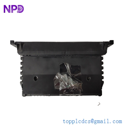
- Model: GE Fanuc IC660TBD025
- Brand: GE Fanuc / Emerson
- Series: Genius I/O System
- Core Function: Terminal assembly for 32-circuit DC discrete sink I/O (New Surplus)
- Product Type: Terminal Base / Wiring Assembly
- Key Specs: 5/12/24 V DC Rated | 32 Circuits | Sink Configuration

GE IC660TBD025
Key Technical Specifications
- Nominal Voltage: 5 V DC (TTL), 12 V DC, or 24 V DC
- Operating Voltage Range: 4.9 to 5.3 V DC (5V mode) or 10 to 30 V DC (12/24V mode)
- Number of Circuits: 32 discrete I/O points
- Input Configuration: Sink type
- Maximum Output Current: 0.5 Amps per circuit
- Inrush Current: 4.0 Amps max for 10 ms
- Isolation: 850 Volts (Block-to-block)
- Power Supply Dropout Time: 4 ms at 12V / 20 ms at 24V
- Heat Dissipation: 11 W (8 inputs) to 18 W (32 outputs max)
- Wiring Terminals: Screw-type terminals (Terminals 5–46)
Installation & Configuration Guide
Phase 1: Pre-Installation
Estimated time: 10 minutes
⚠️ Safety Protocol:
- This is a “Genius” series legacy component. Ensure the Electronics Assembly (IC660EBD025) is detached before mounting the terminal base.
- Verify that field power and block power can be disconnected simultaneously to prevent unexpected startup.
- Check the voltage level of your field devices. Warning: Do not exceed 5.25 V on the +5V terminals to avoid permanent circuit damage.
Preparation:
- Phillips and small flat-head screwdrivers.
- ESD mat and wrist strap.
- Labeling tags for 32 discrete wires.
Phase 2: Removal
Estimated time: 10 minutes
- Unlatch Electronics: Use the release levers on the IC660EBD025 module to separate it from the terminal assembly.
- Wiring Audit: The D025 terminal block has 46 screw terminals. Label each wire (Terminals 5–46) clearly. Terminal 5–32 are generally field device connections.
- Detaching: Unscrew the mounting screws holding the terminal assembly to the sub-panel or DIN rail adapter.
Phase 3: Installation
Estimated time: 20 minutes
- Mounting: Secure the IC660TBD025 to the panel. Ensure there is at least 2 inches of clearance around the block for heat dissipation (up to 18 W max).
- Field Wiring:
- Connect the Genius Bus (Serial 1, Serial 2, Shield In/Out) to terminals 1–4.
- For Sink Configuration: Connect one wire of the field device to a terminal (10–41) and the other wire to the DC power source.
- Tighten screws to 0.5 N·m (approx 4.4 in-lbs).
- Connect Electronics: Align the IC660EBD025 electronics assembly with the terminal base and press firmly until it clicks.
Phase 4: Power-On & Testing
Estimated time: 15 minutes
- Power Verification: Measure the input voltage at the power terminals. Typical draw is 150 mA.
- LED Status:
- Unit OK: Should be solid. If flashing, check the Hand-Held Monitor (HHM) port for error codes.
- I/O Enabled: Illuminates when the bus controller starts communication.
- Diagnostics: Use a Hand-Held Monitor (IC660HHM501) or the PLC programming software to verify the “Switch Fault” status and pulse test settings.
Customer Cases & Industry Applications
Case 1: Legacy Paper Mill Control Restoration
Situation: A paper mill in the Midwest was running a 25-year-old GE Series 90-70 PLC system using Genius I/O. A terminal assembly (IC660TBD025) suffered mechanical damage to the screw terminals during a routine maintenance check, leading to intermittent signal loss on the drying line.
Task: Since the Genius line is discontinued, the mill faced a $50,000 upgrade to RX3i I/O. They needed a direct “Plug-and-Play” replacement to keep the existing cabinet wiring intact.
Action: We provided a New Surplus IC660TBD025 unit from our strategic stock. We verified the terminal revision to ensure compatibility with their existing IC660EBD025 electronics.
Result: The replacement was completed in 45 minutes without any software changes. The mill avoided a week of downtime and the massive expense of a full system migration.
Frequently Asked Questions (FAQ)
Q1: Is the IC660TBD025 a standalone module? A: No. The IC660TBD025 is only the Terminal Assembly. To function, it must be paired with an Electronics Assembly (IC660EBD025). Together, they form the IC660BBD025 I/O Block.
Q2: What is the difference between Sink (D025) and Source (D024) blocks? A: The D025 (Sink) block receives current from field devices. If your sensors or switches provide the voltage (“Source”), you need the Sink block to complete the circuit. If you need to provide power to the field devices, use the IC660TBD024.
Q3: Can I use this for 110V AC signals? A: Absolutely not. This terminal assembly is strictly for DC voltages (5/12/24V). Applying AC voltage will destroy the isolation barrier and the electronics assembly.
Q4: The part is discontinued; are these “New Surplus” units reliable? A: Yes. In my experience, these GE Genius blocks are built like tanks. As a Spare Parts Manager, I ensure every unit undergoes a “Terminal Continuity Test” to check for cracked traces or loose screw sockets before shipping.
Q5: How do I address this block on the Genius bus? A: The address is stored in the Electronics Assembly, not this terminal block. When you swap the terminal assembly, the address remains with the electronics. If you replace both, you will need a Hand-Held Monitor (HHM) to set the Block ID (1–31).