Description
- Model: GE IS200STAOH2AAA (Functional Acronym: STAO)
- Brand: General Electric (USA)
- Series: Mark VI Speedtronic Turbine Control
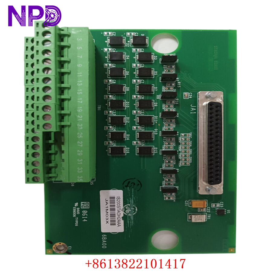
- Core Function: Termination block for field analog output loops, handling signal conditioning and surge protection, New Surplus condition
- Type: Simplex Analog Output Terminal Board
- Key Specs: 8 simplex analog output channels (0-20 mA or 4-20 mA), 2 barrier-type terminal blocks (48 points total), passive board routing to VAOC processor card
- Analog Output Channels: 8 channels, non-isolated simplex configuration
- Signal Output Range: Configurable for 0-20 mA or 4-20 mA standard industrial loops
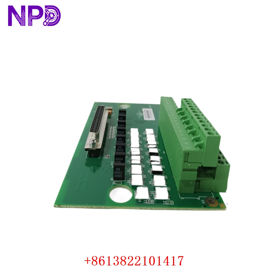
- Field Wiring Terminals: Two barrier-type terminal blocks, 24 points each (total 48 points), accepting up to 12 AWG wire size
- Interface Connectors: 1x 37-pin D-type subminiature connector (JR1) for ribbon cable link to the VAOC processor card
- Surge Protection: Onboard Metal-Oxide Varistors (MOVs) and noise suppression capacitors on every field circuit line
- Maximum Loop Load Resistance: 500 \Omega at 20 mA loop current output
- Calibration Tracking: Integrated on-board serial EEPROM storing board identification, revision history, and factory calibration data
- Power Requirements: Passive operation; draws current loop excitation directly from the linked VAOC card via ribbon cable
- Form Factor Layout: Standard flat-panel mounting layout with integral nylon standoff supports
- Operating Temperature Range: -30 °C to +65 °C
GE IS200STAOH2AAA
GE IS200STAOH2AAA
GE IS200STAOH2AAA
Application Scenarios & Pain Points
In power plants and heavy industrial facilities utilizing GE Mark VI gas or steam turbine control systems, the STAO board serves as the final physical interface to field equipment like valve positioners, variable frequency drives, or I/P transducers. If a field wiring mistake or external electrical transient strikes this interface, it blows the onboard protection components. When an output channel goes dead, the turbine controller loses its ability to throttle critical fuel or steam valves, leading to unstable loop controls or a full generator unit trip. Locating an exact matching replacement revision is vital for plant engineers; a mismatch on this terminal tier can cause improper scaling or configuration errors inside the control room.
Typical Application Scenarios
- Power Generation – Gas/Steam Turbine Fuel Control
Routes 4-20 mA throttle commands directly from the processor card to hydraulic actuator positioners or fuel gas control valves.
- Industrial Controls – Compressor Surge Prevention
Interfaces with high-speed pneumatic blow-off and surge protection valves to protect multi-stage industrial compressor packages.
- Combined Cycle Power Plants – Auxiliary Loop Regulation
Manages automated analog setpoint signals heading to variable speed feedwater pumps and auxiliary steam conditioning systems.
Real-World Field Case: Resolving a Blown Valve Actuator Loop
Background: A combined-cycle power station in central China was executing a routine cold-start sequence when a major electrical storm passed near the high-voltage substation yard. An inductive surge traveled back down an unshielded field line right into the main turbine control enclosure.
The Problem: Channel 3 on the running Mark VI STAO board failed instantly. The 4-20 mA signal output dropped to flat zero, which caused a critical steam extraction valve to latch into its default fail-safe position. The HMI screen began signaling a hard “Analog Output Loop Open Circuit / Circuit Failure” alarm code. Because the turbine could no longer throttle the steam valve, the automated start sequence was blocked, leaving the utility unable to meet peak grid demands.
The Solution: The lead instrument technician contacted our engineering desk. We pulled a clean, unused IS200STAOH2AAA board from our climate-controlled warehouse, verified loop circuit path resistances, checked the integrity of the JR1 connector tracking pins, and dispatched it via a same-day hot-shot delivery carrier.
The Result:
- Delivery Timeline: The replacement board was delivered directly to the plant’s security gate within 14 hours.
- Implementation: The instrument team transferred the field wires to the new terminal blocks, re-connected the 37-pin ribbon cable, and booted up the control rack. The system recognized the on-board EEPROM data, cleared the loop error code, and the startup routine resumed with full automation control restored.
Compatible Replacement Models
When replacing terminal cards in the Speedtronic Mark VI architecture, pay close attention to the functional versions and layout configurations to avoid installation errors.
- IS200STAOH2AAA (Exact Revision) → Direct Drop-in Replacement
- Differences: This represents the standard Revision H2A configuration. It uses classic, high-reliability barrier terminal blocks with screw terminals.
- Action: Move field wires point-to-point and connect the JR1 ribbon assembly. No system configuration re-mapping required.
- IS200STAOH1AAA → Mechanical Check Needed
- Differences: The H1A version features Euro-style pluggable terminal blocks instead of fixed barrier strips. While functionally identical internally, the wiring approach and connector style differ.
- Action Required: If substituting an H1A variant with an H2A model, you must remove the screw plug assemblies and terminate the wires directly onto the fixed barrier strip terminals.
Troubleshooting Quick Reference
Use this diagnostic reference table to isolate issues on the STAO board during field troubleshooting procedures.
| Field Observation | Probable Root Cause | Board Component Relevancy | Field Diagnostic Test Steps | Action / Fix Protocol |
| A single channel reads 0 mA; other loops are normal | Blown onboard fuse trace or failed MOV protection | ✅ High | Disconnect field wires. Connect a milliamp meter directly across the board terminals and read the output state. | If output reads 0 mA but the upstream VAOC card indicates active signal generation, the onboard protection trace is open. Replace the STAO board. |
| All 8 analog outputs drop to zero simultaneously | Disconnected JR1 link or failed VAOC core module | ❌ Low | Inspect the 37-pin ribbon cable connection at both ends. Verify that the main VAOC card is getting 24 V DC power. | Re-seat the JR1 ribbon cable connectors. If the fault persists across all channels, investigate the upstream processing board. |
| Erratic or drifting signals on a specific loop | Induced noise or improper cable shielding | ⚠️ Medium | Verify that the field cable shield line is grounded at only one end (typically at the terminal cabinet frame). | Isolate the analog signal line from high-voltage AC cables. Replace damaged field shielding loops if noise readings remain high. |
| Software reports “Terminal Board ID Mismatch” | Damaged serial EEPROM tracking chip on the board | ✅ High | Read the hardware diagnostic flags inside Toolbox software to view the board ID string data. | If the chip is corrupted or unreadable due to a localized surge, the system will block loop execution. Replace the STAO module. |
❗ WIRING AND HANDING WARNING: Always label and mark every single field conductor bundle clearly before loosening the terminal screws on your old board. Terminal blocks on the IS200STAOH2AAA are non-pluggable; transferring wires one by one to the exact corresponding pin numbers prevents incorrect signal routing and guards against accidentally blowing field positioners during restart.
If your plant floor technicians need to verify our current inventory’s exact firmware compatibility profiles or require a detailed walkthrough of our automated validation processes before placing a shipment block, connect with our support desk today. We will deliver the data you need within two hours.