Description
Product Specifications
- Origin: United States (USA)
- Weight: 1.80 lbs (0.82 kg)
- Dimensions: 11.25 inches x 4.25 inches x 1.5 inches
- Input Capacity: 24 dry contact inputs
- Excitation Voltage: Supports 24 VDC, 48 VDC, and 125 VDC nominal excitation configurations.
- Compatibility: Designed for GE Mark VI Speedtronic control systems.
- Redundancy: Supports Simplex, Dual, and TMR (Triple Modular Redundant) system architectures.
The GE IS200TBCIS2CCD is a high-density contact input terminal board that facilitates the interface between field-level discrete switches and the Mark VI control system. This “CCD” revision is specifically engineered for high-integrity monitoring, featuring dual terminal blocks for secure field wiring and specialized onboard filters to suppress electrical noise and contact bounce. It works in conjunction with a specialized I/O processor (such as the VCMI or VTCC) to provide the control logic with real-time status updates from E-stops, limit switches, and auxiliary contacts, ensuring precise sequence-of-events (SOE) recording with millisecond accuracy.
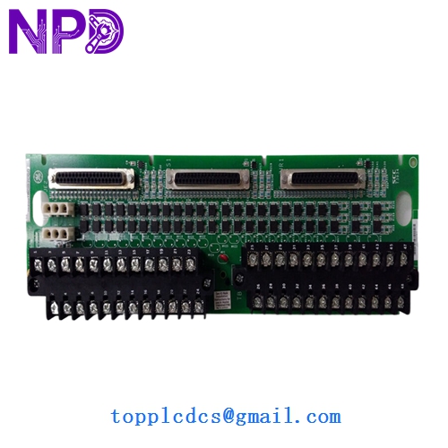
GE IS200TBCIS2CCD
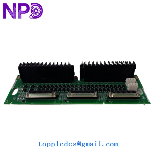
GE IS200TBCIS2CCD
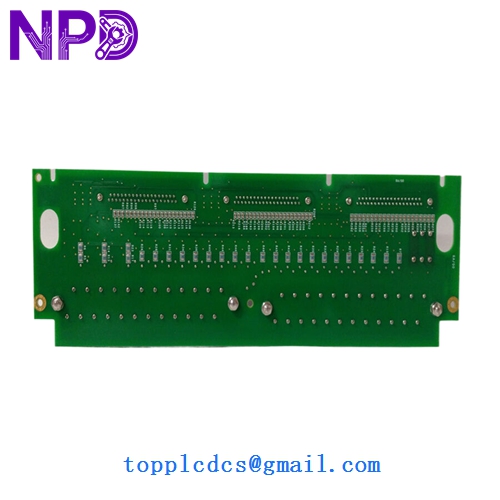
GE IS200TBCIS2CCD
Model Comparison: IS200TBCIS2CCD vs. Similar Models
The IS200TBCIS2CCD is distinguished from the base TBCIS1C model by its expanded voltage compatibility and specific hardware revision level. While the TBCIS1 series typically supports a narrower range of excitation voltages, the TBCIS2 (and specifically the CCD version) is designed with more robust isolation components to handle 125 VDC battery systems common in utility-scale power plants. Additionally, the “CCD” suffix denotes a later manufacturing standard with enhanced surface-mount reliability and improved surge protection over earlier “AAA” or “BBB” iterations, making it the preferred choice for modernizing legacy turbine control panels.
Operational Guidelines
- Excitation Matching: Before commissioning, verify that the onboard jumpers or hardware settings match the field excitation voltage (e.g., 24V vs 125V) to prevent logic errors or hardware damage.
- SOE Accuracy: To ensure accurate Sequence of Events (SOE) time-stamping, use shielded twisted-pair cabling and ensure the overall cable length stays within the system’s capacitance limits.
- Contact Type: This board is designed for “Dry Contacts”; do not apply external powered signals directly to the input terminals without verifying the specific wiring diagram for your cabinet.
- Terminal Torque: Use a calibrated screwdriver to tighten terminal block screws to 5-7 in-lb; over-tightening can crack the PCB traces, while loose connections can lead to intermittent “Input Open” diagnostics.