Description
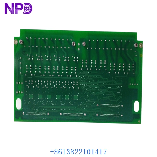
- Model: GE IS200TRLYH1BGF
- Brand: General Electric (GE)
- Series: Mark VI Speedtronic Control System
- Core Function: Relay output termination and solenoid driving
- Product Type: Termination Relay Board (TRLY)
- Key Specs: 12 Magnetic Relays TMR/Simplex Compatible Fused Outputs
- Relay Count: 12 plug-in magnetic relays
- Contact Channels:
- Relays 1–6: Form C (Changeover) contacts
- Relays 7–12: Form A (Normally Open) contacts
- Fusing: Each output is individually protected by a 10 A glass fuse
- Feedback: Built-in “contact sensing” to verify relay position back to the controller
- Connectors: Two 37-pin D-type connectors (JR1 and JS1) for interface with VCRC/VRLY cards
- Voltage Rating: Typically 24 V DC, 125 V DC, or 120 V AC (application dependent)
- Manual Control: Supports manual solenoid testing via local jumpers/switches (on specific revisions)
- Mounting: Standard Mark VI terminal board rack or standoff mounting
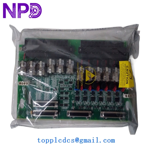
GE IS200TRLYH1BGF
GE IS200TRLYH1BGF
GE IS200TRLYH1BGF
Application Scenarios & Pain Points
In the GE Mark VI ecosystem, the IS200TRLYH1BGF is the heavy-duty interface between the digital logic and the physical world. It is the board that actually fires the fuel gas solenoids, starts the lube oil pumps, and triggers the fire suppression systems. Because it handles high-current inductive loads, the TRLY board is a common point of failure during electrical storms or field-side short circuits. When a relay welds or a fuse blows, it can stop a 100 MW turbine in its tracks.
Typical Application Scenarios:
- Solenoid Valve Control Managing the trip solenoids and fuel skid isolation valves for gas and steam turbines.
- Motor Starter Interfacing Driving the contactors for auxiliary systems like cooling fans and hydraulic pumps.
- Alarm Annunciation Triggering physical horns, beacons, and master trip relays in the control room.
- Inter-system Interlocks Providing dry-contact signals to third-party DCS or BOP (Balance of Plant) systems.
Case Study: The “Fused” Fuel Valve
Background: A power plant in the Middle East reported that a fuel gas vent valve refused to open during the purge cycle, preventing the turbine from starting.
Problem: The software showed the command was active, but no voltage was reaching the valve. Upon inspecting the IS200TRLYH1BGF, we found that the output fuse (F1) was blown. However, simply replacing the fuse caused it to pop again immediately. We discovered that the internal relay contacts had carbonized and were creating an internal short.
Solution: We provided a replacement IS200TRLYH1BGF board and advised the client to check the solenoid coil resistance.
Result: – Startup Success: The turbine successfully entered the purge cycle and ignited.
- Root Cause: A failing solenoid coil was drawing 12 A (exceeding the 10 A fuse rating) and damaging the TRLY board.
- Engineer’s Insight: “If you blow a fuse on a TRLY board, don’t just put a bigger fuse in. The board is telling you the field device is failing. Replace the board and the solenoid to avoid a permanent hardware fault.”
Compatible Replacement Models
The TRLY board has several “H” (Hardware) and “G” (Group) versions. The H1BGF indicates a specific revision that includes specific fuse ratings and relay types.
| Original Model | Replacement Model | Compatibility | Note |
|---|---|---|---|
| IS200TRLYH1BGF | IS200TRLYH1BGF | ✅ Exact Match | Standard 12-relay revision. |
| IS200TRLYH1B | IS200TRLYH1BGF | ✅ Compatible | The “GF” version is often a newer manufacturing revision. |
| IS200TRLYH2A | IS200TRLYH1BGF | ❌ Incompatible | H2 boards often have different contact configurations. |
Troubleshooting Quick Reference
| Symptom | Possible Cause | Relation | Quick Check | Action |
|---|---|---|---|---|
| No field voltage on one channel | Blown Fuse | ✅ High | Check the individual glass fuse (F1–F12). | Replace fuse; check for field shorts. |
| Relay clicks but no power | Burnt Contacts | ✅ High | Measure resistance across terminal blocks when energized. | Replace the TRLY board. |
| “VRLY Diagnostic” Alarm | Feedback Error | ✅ High | Check if the relay state matches the LED on the board. | Verify ribbon cable seating at JR1/JS1. |
| All relays on board dead | Power Supply | ⚠️ Med | Measure 24V DC at the connector pins. | Check the VRLY/VCRC card in the rack. |
❗ Pro Tip: Contact Feedback
One of the best features of the IS200TRLYH1BGF is the contact feedback loop. The Mark VI software doesn’t just “hope” the relay closed—it actually senses the voltage across the contacts. If your HMI shows a “Relay Feedback Mismatch,” it means the logic sent a ‘Close’ command but the physical relay is either stuck open or the fuse is blown.
Wiring & Installation:
- Photo Documentation: Before swapping, take a clear photo of the 36+ wires landed on the terminal blocks.
- Relay Seating: If you receive a new board, gently press down on each of the 12 relays. They can sometimes vibrate loose during international shipping.
- Safety First: These boards often switch 125 V DC or 120 V AC. Ensure all field power is locked out before touching the terminal screws to avoid accidental turbine trips or electrical shock.