
Description
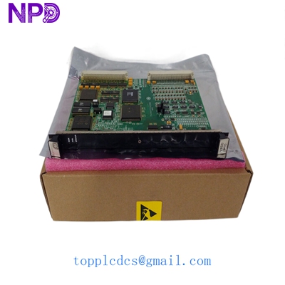
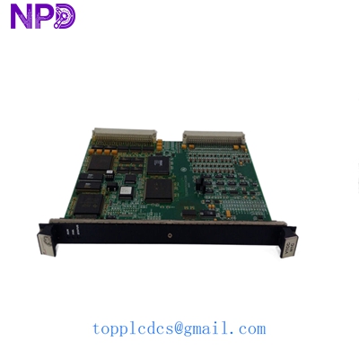
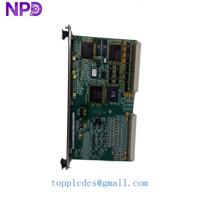
- Model: GE IS200VTCCH1CBB
- Brand: General Electric (USA)
- Series: Mark VI Turbine Control System
- Core Function: Processes 24 thermocouple inputs for turbine monitoring
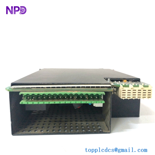
- Product Type: I/O Board / Thermocouple Input Module
- Key Specs: 24 channels | Supports J, K, T, E types | Cold junction compensation
- Thermocouple Channels: 24 differential inputs
- Input Types: Supports J, K, T, E, S, R, and B types
- Resolution: 14-bit A/D conversion
- Scan Rate: 10 ms to 100 ms (configurable)
- Isolation: Optical isolation between system and field logic
- Cold Junction Compensation: Integrated on-board sensors
- Power Supply: 28 V DC (via VME rack backplane)
- Operating Temp: 0 to 60 °C (32 to 140 °F)
- Connector: 24-point terminal block interface
- Redundancy: TMR (Triple Modular Redundant) architecture compatible
- Safety Rating: Industrial grade for heavy-duty turbine environments
GE IS200VTCCH1CBB
Installation & Configuration Guide
Phase 1: Pre-Installation (Preparation) Estimated Time: 10 minutes
⚠️ Safety Protocol:
- Notify the control room that the Mark VI rack will be accessed.
- In a TMR system, verify that the other two processors are healthy before pulling a card.
- Use a grounded ESD wrist strap and a static-dissipative mat.
Tools & Backup:
- Small flathead screwdriver for terminal blocks.
- Excitation module (If your system requires external CJC or power).
- Take a clear photo of the existing cabling and any physical jumper settings on the old board.
Phase 2: Removal of Faulty Board Estimated Time: 5 minutes
- Unseat Connectors: Gently remove the cables connected to the front of the board. Label each cable clearly.
- Unlock Levers: Locate the plastic ejector tabs at the top and bottom of the board.
- Extraction: Press the tabs outward to unseat the board from the VME backplane. Pull the board straight out along the guide rails.
- Inspection: Check the backplane pins for any debris or damage. Use a can of compressed air to clear dust if necessary.
Phase 3: Installing the New IS200VTCCH1CBB Estimated Time: 10 minutes
- Jumper Match: Compare the hardware jumpers on the new board with your old one. They must match exactly for the thermocouple scaling to work.
- Alignment: Align the board with the rack guides. Slide it in until the connectors touch the backplane.
- Seating: Firmly press the ejector tabs inward to lock the board in place. You should hear a distinct click.
- Re-wiring: Reconnect the input cables based on your photos/labels. Tighten screws to 0.5 N·m.
Phase 4: Commissioning & Validation Estimated Time: 20 minutes
- LED Status: Watch the board status LEDs during the boot sequence. A solid green light usually indicates the board has passed its self-test.
- ToolboxST Check: Open the GE ToolboxST software. The board should appear in the hardware tree. Check for “Board Mismatch” or “Configuration Error” alarms.
- Signal Calibration: Verify temperature readings against a known source or a secondary sensor.
- Final Log: Record the serial number and installation date in the maintenance portal.

GE IS200VTCCH1CBB
Customer Cases & Industry Applications
Case 1: Power Plant Emergency Fault Recovery A combined-cycle power plant in Southeast Asia suffered a sudden trip on a Gas Turbine due to “Loss of Thermocouple Signals.” Diagnosis pointed to a failure in the IS200VTCCH1CBB board. The local OEM branch quoted a 10-week delivery. By sourcing our on-hand surplus stock, the plant received the module via DHL Express in 3 days. We provided the test report showing the board survived a 24-hour load test at 50 °C. The turbine was back online within 72 hours of the initial failure, saving the plant millions in grid penalties.
Case 2: Strategic Inventory for Aging Infrastructure A Middle Eastern utility company operating Mark VI systems noticed an increase in “Lead time variability” for legacy GE parts. They performed an ABC analysis and identified the IS200VTCCH1CBB as a “Critical-A” spare due to its high input density. Instead of waiting for a total failure, they purchased two units as “Buffer stock.” Last year, a lightning strike damaged multiple I/O cards. Because they had the “insurance policy” on the shelf, they avoided a complete system overhaul and extended the life of their current control infrastructure by another 5 years.
GE IS200VTCCH1CBB
Frequently Asked Questions (FAQ)
Q: Is the IS200VTCCH1CBB a hot-swappable board? A: In a Triple Modular Redundant (TMR) Mark VI system, you can technically replace an I/O card while the other two process signals. However, in my experience, it is always safer to power down the specific rack branch or verify the “Simplex” vs “TMR” configuration in ToolboxST. If you’re running a Simplex system, pulling this card will definitely cause a trip.
Q: Does this board require special calibration tools? A: The board features automatic cold junction compensation (CJC). While it is calibrated at the factory, I recommend a loop check using a thermocouple simulator (like a Fluke 754) after installation to ensure the entire signal path from the field to the HMI is accurate within ±1 °C.
Q: Can this board replace an older “A” or “B” revision? A: Generally, the “C” revision is backward compatible with “A” and “B” versions, but you must check your ToolboxST configuration. Sometimes a simple firmware update in the software is required to recognize the newer hardware revision.
Q: Why is your price lower than the OEM’s “New” price? A: We source these from canceled projects and authorized channel surpluses. It’s the exact same GE hardware, just without the “Current Year” production tax. We pass those savings to you while still providing a full 1-year warranty.
Q: Do you offer the terminal blocks (connectors) with the board? A: Most surplus boards do not include the field terminal blocks as those usually stay wired in the cabinet. If your terminal block is damaged, let us know—we can often source those separately.