Description
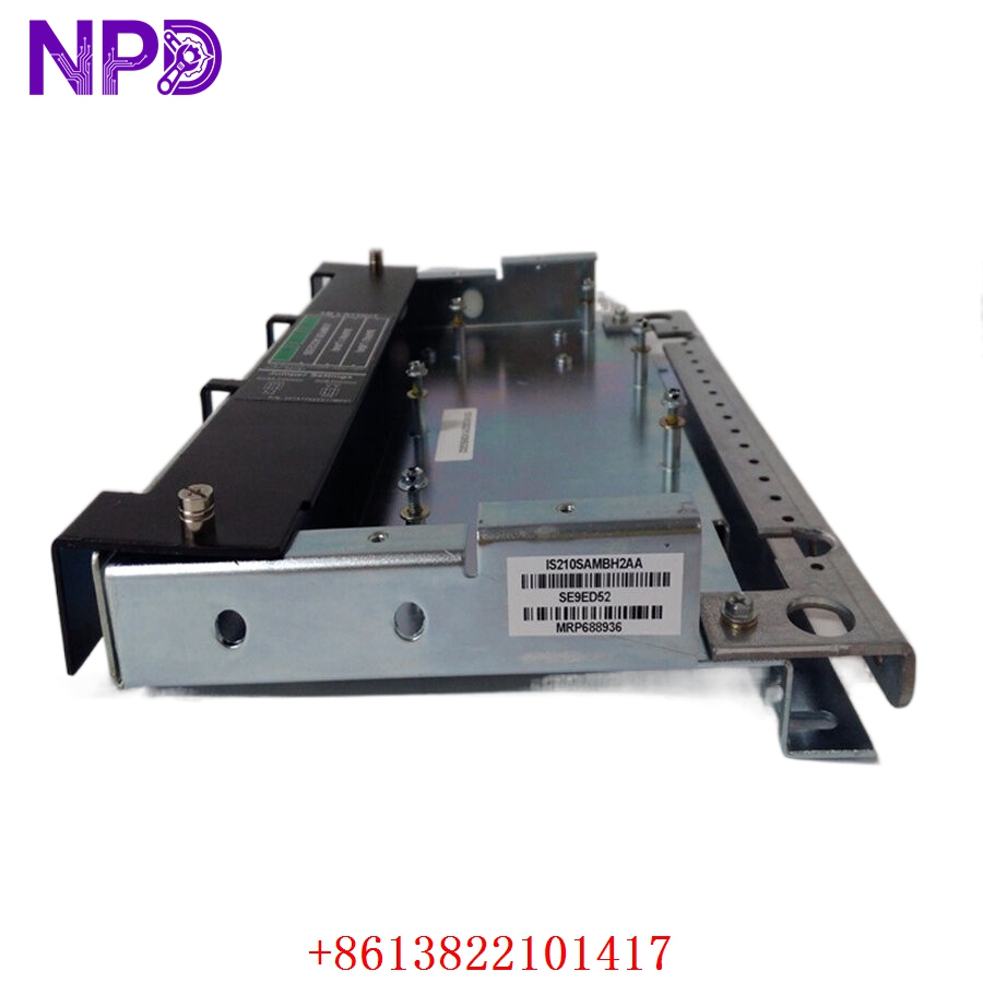
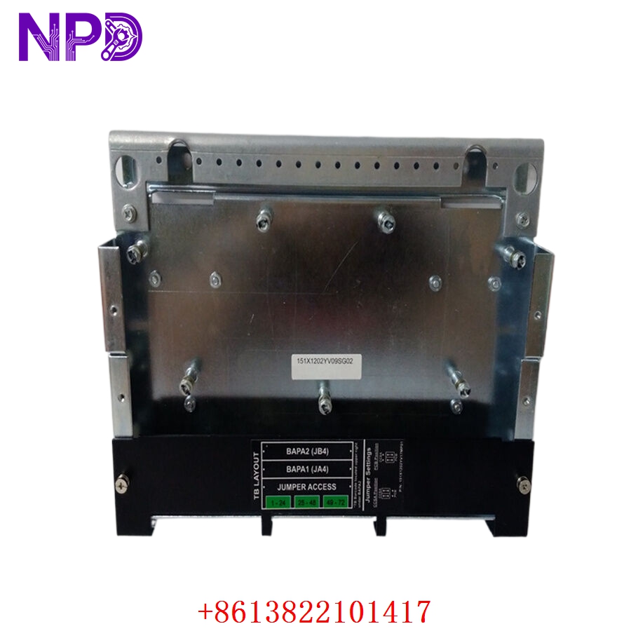
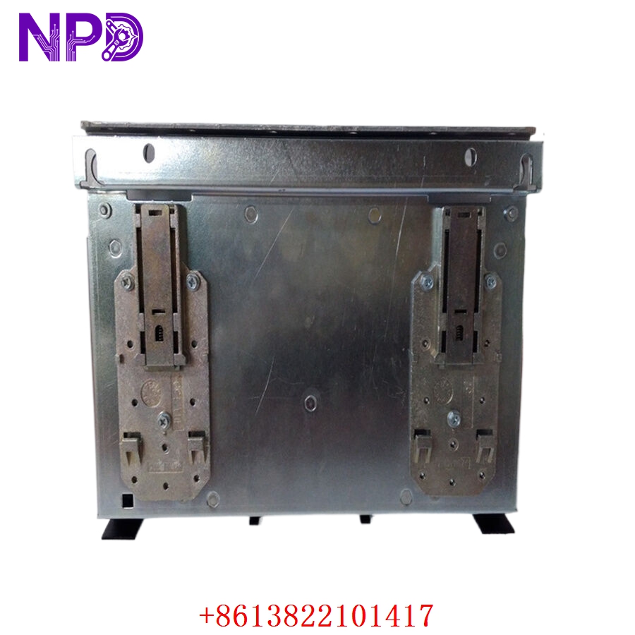
- Model: IS210SAMBH2AA
- Brand: General Electric (GE)
- Series: Mark VIe / Mark VIeS Control Systems
- Core Function: Acoustic monitoring and combustion dynamics terminal interface
- Condition: Brand New Surplus (Original authentic warehouse stock, zero run-time hours)
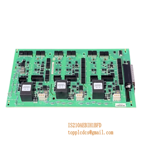
- Product Type: Dedicated Signal Terminal Board
- Key Specs: Multi-channel dynamic pressure inputs | High-frequency noise filtering | High-density ribbon interface
- Application Domain: Real-time acoustic wave monitoring across gas turbine combustion chambers
- Input Configuration: Supports specialized high-temperature dynamic pressure transducers and charge amplifiers
- Noise Suppression: On-board analog bandpass and anti-aliasing hardware filters
- System Interfacing: Dual high-density ribbon connectors routing directly to Mark VIe I/O packs
- Isolation Engineering: High-integrity trace isolation preventing field ground loops from hitting logic circuitry
- Shielding Framework: Integrated heavy-duty metal chassis plate for electromagnetic interference (EMI) suppression
- Environmental Tolerance: Rated for stable operation up to +60°C within sealed control enclosures
- Channel Capacity: Multi-point simultaneous input tracking for comprehensive combustor can coverage
- Physical Profile: Compact surface-mount board layout designed for standard rack-mount backplane pairing
GE IS210SAMBH2AA
GE IS210SAMBH2AA
GE IS210SAMBH2AA
Installation & Configuration Guide
Phase 1: Pre-Installation (Estimated Time: 15 minutes)
⚠️ Safety Critical Warning:
- The IS210SAMBH2AA board monitors combustion dynamics. Operating the gas turbine without active acoustic protection can result in catastrophic structural failure within seconds due to resonance. Always verify the turbine is completely shut down and placed in a safe maintenance state before service.
- Isolate all power feeding the specific control panel sector.
- Ensure you have clear access to the engineering workstation running ControlST software for post-replacement validation.
Required Tools & Gear:
- Grounded ESD (Electrostatic Discharge) wrist strap with verified chassis ground connection
- Precision slot-head screwdriver (3.0 mm) for terminal screws
- Industrial digital multimeter (Fluke 179 or equivalent)
- High-resolution camera for configuration logging
Backup Execution:
- Upload and save a current snapshot of the I/O configuration and calibration constants for the associated acoustic tracking slot within the ControlST software suite.
Phase 2: Removal (Estimated Time: 10 minutes)
- Tag the Cabling: Use marker tags to identify every incoming sensor coaxial or shielded twisted-pair cable connected to the terminal strip.
- Disconnect Signal Lines: Loosen the terminal retention screws counterclockwise and gently remove the field wires. Do not yank the wires, as this can fracture older copper conductors.
- Unplug System Interfaces: Carefully squeeze the side latches on the high-density ribbon cables interfacing with the I/O packs, then pull them straight out.
- Unmount the Board: Loosen the structural screws securing the metal chassis backing plate to the enclosure frame. Lift the board clear and slide it directly into an antistatic storage pouch.
Phase 3: Installation (Estimated Time: 15 minutes)
- Static Control: Unpack the new surplus IS210SAMBH2AA only while wearing your grounded ESD wrist strap.
- Verify Hardware Revisions: Confirm the part number on the adhesive tracking label reads exactly IS210SAMBH2AA.
- Mount the Assembly: Position the board against the enclosure grid rails, align the mounting holes, and tighten the structural screws clockwise to roughly 0.5 N·m. Ensure the grounding path between the chassis plate and the enclosure frame is solid.
- Reconnect Interfaces: Press the high-density ribbon cables firmly into the corresponding on-board header slots until the side latches click into place.
- Land the Field Wiring: Terminate the field sensor lines back into their original positions according to your labels and wire tags.
Phase 4: Power-On & Testing (Estimated Time: 30 minutes)
The Commissioning Sequence:
- Conduct a final resistance verification between the terminal signal returns and the chassis frame to ensure no field lines are accidentally shorted to ground.
- Re-energize the control enclosure power supply rails.
- Observe the I/O Pack Status: The indicators on the paired I/O pack modules should transition from initialization states to steady green operations.
- Execute Calibration Check: Open ControlST and navigate to the acoustic tracking diagnostics panel. Verify the sensor bias voltages fall within normal operating limits (typically around 10 V to 12 V DC depending on the specific charge amplifier pairing).
- Run a live signal verification check to ensure baseline background noise levels register properly across all combustion cans before scheduling turbine ignition.
- Record the module replacement date, hardware serial numbers, and technician credentials inside the facility asset ledger.
Customer Cases & Industry Applications
Case 1: Combined Cycle Power Station—Emergency Outage Avoidance
Situation: A 500 MW combined cycle power plant in eastern China experienced a sudden signal breakdown on its gas turbine combustion monitoring network during peak summer demand. The active Mark VIe system reported a permanent open-circuit fault on the acoustic sensor inputs, tracing back to a failed input filter track on the terminal board.
Task: Without functional acoustic monitoring, the plant’s operating permits required an immediate controlled shutdown of the gas turbine within 24 hours to prevent unmonitored combustion dynamics from damaging the machine. A forced shutdown during peak grid demand meant facing over $110,000 per day in direct power revenue losses and grid non-compliance penalties.
Action: The plant’s controls engineer contacted our distribution depot after finding our verified stock of GE components. We confirmed a brand new surplus IS210SAMBH2AA was ready in our warehouse. Our logistics team expedited the customs clearance and packing process, dispatching the board via a priority overnight courier service.
Result:
- Delivery Speed: The board arrived at the facility within 18 hours of the initial call.
- Outcome: The maintenance crew completed the physical swap during a scheduled low-demand night window. The new board initialized perfectly, cleared the open-circuit alarm state, and allowed the plant to maintain its generation commitments through the peak summer window.
Case 2: Cogeneration Plant—Preventative Maintenance Capital Efficiency
Situation: An industrial cogeneration facility operating an older GE Frame 6 gas turbine was managing an upgrade plan for its auxiliary controls infrastructure. The OEM recommended a full terminal and I/O framework modernization, quoting a package price exceeding $140,000 with a lengthy lead time.
Task: The facility’s long-term asset strategy called for a complete site relocation or retirement within 4 to 5 years, making a major capital upgrade financially unviable. However, the existing acoustic monitoring board was showing signs of terminal degradation from years of high-vibration exposure, and a reliable spare was required immediately to satisfy insurance compliance.
Action: We worked with their procurement team to source an original new surplus IS210SAMBH2AA terminal assembly from our central reserves, bypassing the inflated pricing and extended delivery timelines of the standard market paths.
Result:
- Capital Preserved: Saved more than 80% in capital outlays compared to the proposed system overhaul.
- Operational Protection: The facility secured an authentic, un-degraded spare board to serve as a reliable drop-in solution, keeping the existing turbine safety system fully compliant with corporate risk standards for its remaining operational lifecycle.
Frequently Asked Questions (FAQ)
Q1: What specific role does the SAMB board play in combustion safety?
A: The SAMB (Acoustic Monitoring Board) is the physical interface that connects dynamic pressure transducers located on the turbine combustor cans to the digital processing core of the Mark VIe system. It captures raw high-frequency pressure fluctuations (combustion acoustics). If these oscillations match the mechanical resonance frequency of the combustor liners, they can cause fast, catastrophic structural cracking. The SAMB filters and isolates these specific wave patterns so the controller can modify fuel ratios or trip the machine before damage occurs.
Q2: Can the IS210SAMBH2AA be hot-swapped while the turbine is running?
A: No. The IS210SAMBH2AA is a termination assembly that routes active, low-voltage analog inputs from field instrumentation straight to the processing modules. Pulling or replacing this board while the system is under power will break the safety monitoring loop, instantly triggering a master turbine trip. Always perform this replacement when the control core is completely powered down and bypassed.
Q3: What is the significance of the “H2AA” revision code compared to an older “H1A” board?
A: The H2AA identifier denotes a production group update implemented by General Electric. It retains the exact same physical dimensions, mounting hole layout, and terminal wiring positions as the original H1A model, making it a completely backward-compatible drop-in replacement. The H2 update features optimized component tolerances and enhanced trace layouts designed to maximize signal stability in high-ambient-temperature control cabinets.
Q4: Why should we source a Brand New Surplus unit instead of a lower-cost repaired board?
A: For a critical protection system like combustion dynamics, using a repaired or refurbished board introduces unquantifiable risks. A repaired unit has typically been subjected to thousands of hours of thermal and vibration stress before failing. While a single broken component may have been patched, the rest of the board’s capacitors, resistors, and solder joints remain aged and prone to premature failure. Our Brand New Surplus stock consists of un-deployed, zero-hour hardware that delivers original factory reliability.
Q5: How do you verify the quality of an obsolete or legacy terminal board?
A: Every terminal board entering our warehouse must pass an explicit validation protocol:
[Inbound Source Traceability Audit] -> [Microscopic Trace & Solder Joint Review] -> [Parametric Continuity Testing] -> [ESD Sealing & Logging] We carefully verify that all trace paths, filter networks, and ribbon header pins match factory electrical specifications. We do not use guesswork; we ensure the hardware is physically pristine and ready to perform reliably from the moment you install it.