

Description
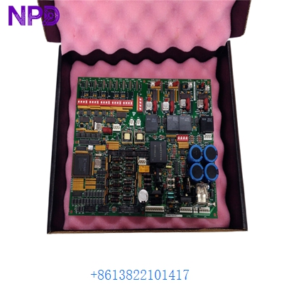
GE IS215ACLEH1B is a high-performance Application Control Layer Module (ACLM) engineered for deployment within General Electric Speedtronic turbine control and EX2100/EX2100e excitation control architectures. Designed to execute real-time control algorithms and manage system-level communication, this microprocessor-based module coordinates critical control logic, safety interlocks, and network data exchange across heavy-duty power generation facilities.
Product Specifications (Datasheet)
- Brand: GE (General Electric / Industrial Systems)
- Model: IS215ACLEH1B (Compatible with variant revision suffixes)
- Series: Mark VI Speedtronic Turbine Control / EX2100e Excitation Series
- Product Name: Application Control Layer Module (ACLM)
- Place of Origin: United States
- Lifecycle Status: Specialized Industrial Supply / Active Legacy Replacement
- Processor Architecture: High-speed 32-bit microprocessor with integrated PCI controller
- Memory Architecture: Includes Level 2 cache, non-volatile flash memory for parameter storage, and RAM
- Communication Interfaces: Onboard 10BaseT Ethernet port (RJ45 interface) and support for internal control networks (ISBus)
- Enclosure Form Factor: Modular printed circuit board designed to occupy standard rack or cabinet half-slots
Operating Guidelines and Usage Methods
Proper integration and handling of application control modules require strict adherence to standard electronic safety and rack installation procedures.
- ESD Precautions: Always utilize a certified grounded electrostatic discharge (ESD) wrist strap when handling the printed circuit board to protect sensitive internal microprocessors, flash memory, and surface-mount logic from static damage.
- Secure Seating & Alignment: Ensure the module is firmly aligned and securely seated into its designated rack slots or backplane connectors before locking retention mechanisms and applying power.
- Environmental Control: Operate the host control cabinet within a clean, climate-controlled environment shielded from excessive humidity, airborne dust, and severe temperature fluctuations [-30°C to +65°C operating range].
Power-On and Power-Off Sequence
Adhering to correct energization protocols prevents electrical transients and protects internal processing components.
- Power-On Sequence:
- Confirm that all internal communication cables, backplane connections, and front-panel Ethernet links are securely attached to the module.
- Switch on the primary cabinet power distribution feeds supplying the control rack.
- Monitor onboard diagnostic LED indicators and operator workstation software to verify normal BIOS initialization, software loading, and network communication polling.
- Power-Off Sequence:
- Safely take the affected turbine control loops or excitation regulation processes offline via the ControlST or configuration software.
- Power down the main electrical feeds supplying the system control enclosure.
- Allow adequate time for internal circuits and filter capacitors to fully discharge before servicing or unseating the module.
Product Instructions
The IS215ACLEH1B manages application-level tasks, such as executing core turbine control logic, processing analog/digital signals, and overseeing network communications over Ethernet and ISBus. It supports online configuration loading and I/O forcing for diagnostic purposes. Periodically inspect edge connectors and diagnostic status LEDs during scheduled maintenance windows to ensure uninterrupted operational reliability.
Frequently Asked Questions (Q&A)
- Q: What system utilizes the IS215ACLEH1B module?
- A: It is deployed within GE Mark VI turbine control systems and EX2100e excitation regulation architectures.
- Q: What is the primary function of the ACLM board?
- A: It acts as an application-level controller handling real-time control logic, safety protocol execution, and data communication across plant networks.
- Q: What should I check first if communication or processing faults occur?
- A: Verify the physical seating of the module in its rack slot, check front-panel Ethernet link indicators, and review diagnostic error codes via the configuration software.