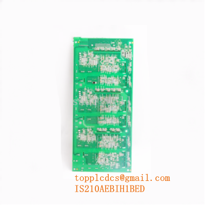
Description
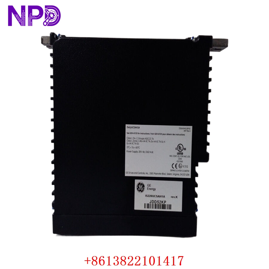
- Model: IS230STAOH2A
- Brand: General Electric (GE)
- Series: Mark VIe / Mark VIeS Speedtronic Turbine Control Systems
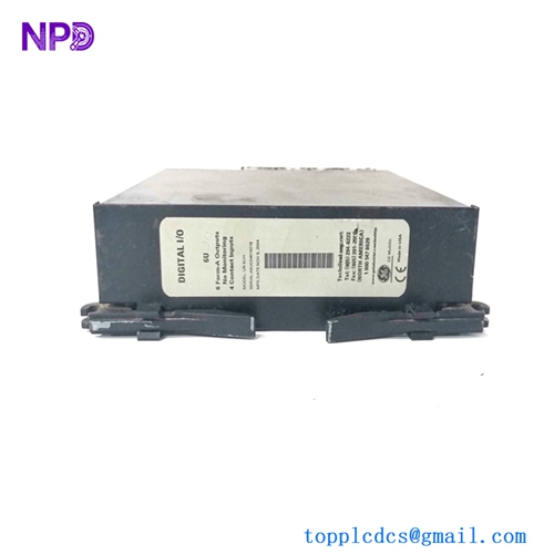
- Core Function: 8-Channel Analog Output Terminal Interface
- Condition: Brand New Surplus (Pristine factory original, zero hours of active service)
- Product Type: Analog Output Termination Module
- Output Ranges: Supports standard industrial loop configurations including 0-20 mA and 4-20 mA current control signals.
- Channel Density: Houses 8 independent, fully programmable analog output channels. The first two channels (Outputs 1 and 2) are equipped with additional hardware configurations to interface directly with 0-200 mA specialized servo valve drivers.
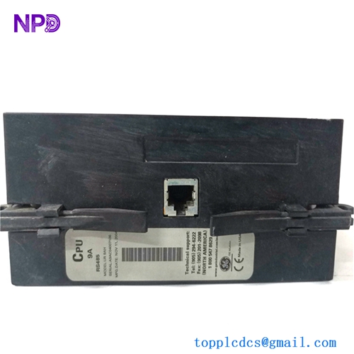
- System Redundancy Support:
- In Simplex Layouts, it communicates via a single high-density cable directly to a PAOC Analog Output I/O pack.
- In Triple Modular Redundant (TMR) configurations, the board distributes the field signals to three distinct I/O packs (R, S, and T branches) for high-integrity hardware voting.
- On-Board Diagnostics: Continuously tracks loop currents and output voltages across every terminal path, monitoring for open-circuit wiring, line resistance degradation, or unexpected control loop failures.
- Surge & Noise Suppression: Built-in metal-oxide varistors (MOVs) and specialized high-frequency decoupling capacitor networks guard the delicate internal logic bus from severe electrical spikes and high field EMI.
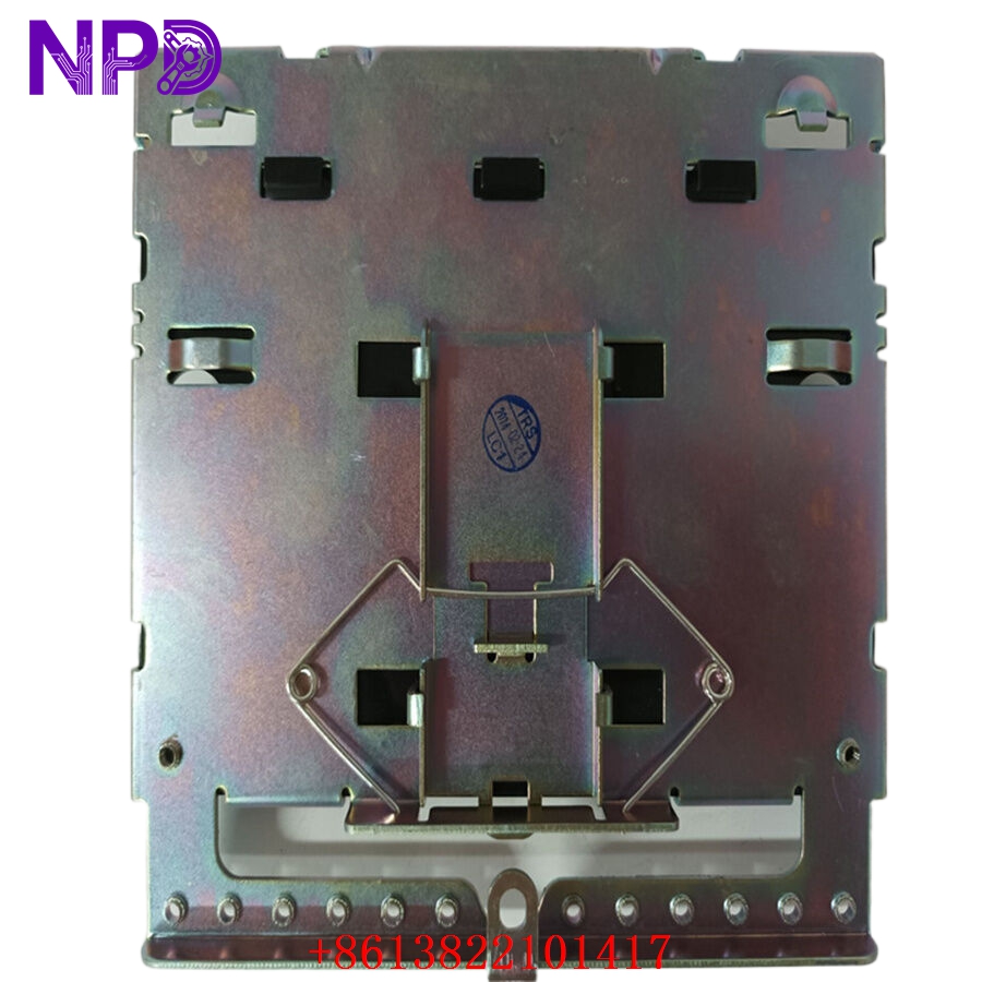
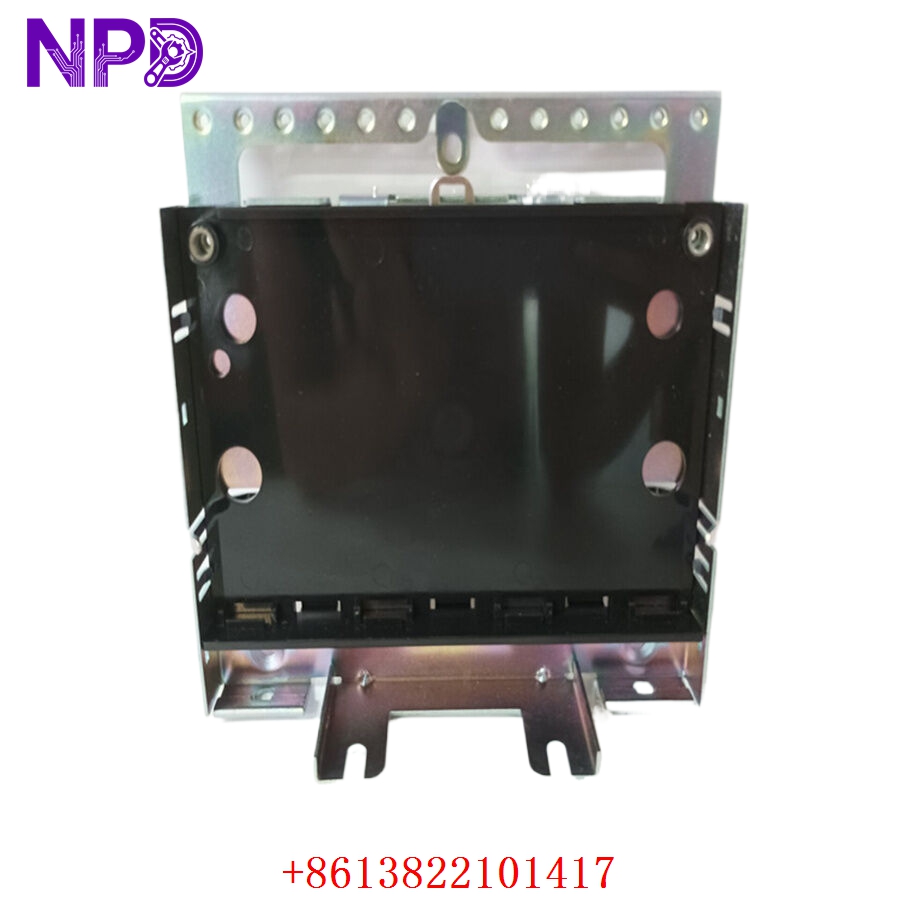
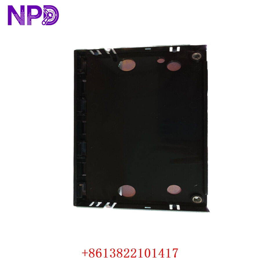
- Physical Interface: Built onto a heavy-duty sheet-metal mounting chassis designed for direct mounting inside cabinet structural channels, with integrated ground-plane tracking.
GE IS230STAOH2A
GE IS230STAOH2A
GE IS230STAOH2A
GE IS230STAOH2A
Installation & Configuration Guide
Phase 1: Pre-Installation (Estimated Time: 15 minutes)
⚠️ Safety Critical Warning:
- The IS230STAOH2A manages active analog output channels which frequently control proportional fuel valves, guide vanes, or critical governor actuators. Replacing this board on a live system without comprehensive loops being set to safe, manual, or bypassed isolation modes can cause sudden turbine overspeed or localized physical damage.
- Ensure full electrical lockout/tagout (LOTO) protocols are active on the auxiliary power lines driving the connected 24 V DC loops.
Required Toolkit:
- Grounded ESD dissipative wrist strap (mandatory)
- Slotted terminal tool (2.5 mm precision tip)
- Digital loop calibrator / Process meter (e.g., Fluke 789 ProcessMeter)
- Clean antistatic workspace mat
Phase 2: Removal (Estimated Time: 10 minutes)
- Document Current Wiring: Take clear reference notes or photograph the layout of the current field loops landed on the terminal block strips.
- De-energize Field Connections: Open the upstream fuse blocks or isolation links feeding power into the output signal paths.
- Disconnect I/O Cables: Squeeze the retention clips on the high-density cables routing back to the PAOC processing modules, sliding them smoothly out of their headers.
- Unmount the Assembly: Back out the holding screws that fix the metal chassis backing plate to the cabinet grid frame, and lift the assembly safely clear into an ESD protective bag.
Phase 3: Installation (Estimated Time: 15 minutes)
- Verify Jumper Positions: Lay the new surplus IS230STAOH2A on your antistatic mat and confirm that any on-board configuration pins or jumpers precisely mirror your plant’s engineering blueprint layout.
- Secure the Chassis: Position the module backing framework over the rack layout coordinates and tighten down the mounting hardware to 0.5 N·m to ensure perfect seismic/vibration anchoring.
- Engage System Links: Snap the high-density system connection plugs into the on-board headers until the retaining clips click shut.
- Land Field Wiring: Wire the analog loops carefully back onto the terminal strips using your documentation notes, ensuring shielding braid drains are correctly grounded.
Phase 4: Commissioning & Validation (Estimated Time: 25 minutes)
The Power-On Protocol:
- Restore primary operational power rails to the associated control column.
- Review LED Status arrays: Confirm that the paired PAOC processing units boot successfully without displaying configuration mismatches or active loop fault errors.
- Execute Parametric Loop Checks: Utilize the ControlST platform to run manual step-commands (e.g., injecting 4 mA, 12 mA, and 20 mA test values) while confirming physical output accuracy directly on the terminals using a precision multimeter.
- Once the loops track smoothly within ±0.1% full-scale tolerances, return the control logic back to automated tracking states.
- Record the replacement timeline, serial parameters, and hardware tracking codes inside your local engineering history register.
Frequently Asked Questions (FAQ)
Q1: Can a single IS230STAOH2A board be shared by both Simplex and TMR configurations?
A: Yes. The IS230STAOH2A board is designed with specialized parallel trace routing that natively allows it to connect either to a single I/O pack (Simplex operation) or to split those same physical field terminals cleanly across three independent I/O packs (TMR architecture). The hardware selection is determined automatically by the number of system cables connected and your settings within the ControlST software environment.
Q2: What type of analog signals can this specific board manage?
A: The board primarily interfaces with standard 4-20 mA and 0-20 mA current loops used for general control actuators. However, channels 1 and 2 feature customized internal shunts and scaling pathways optimized to handle high-current servo control applications (up to 200 mA) for precise electro-hydraulic valve positioning.
Q3: What is the benefit of the “H2A” revision over older version designs?
A: The H2A group revision incorporates higher-density electronic surface-mount components that provide better thermal efficiency and less signal drift when panels operate in hot environments. It features the exact same mounting footprint and terminal arrangement as older revisions, making it a drop-in replacement that requires no physical layout redesign or panel modification.