Description
- Product Parameters
- Model Number: IS230TVBAH2A
- Series: Mark VIe Speedtronic
- Board Type: Vibration Termination Board (TVBA)
- Input Channels: 14 Vibration/Position channels (Supports Prox probes, Velomitors, Accelerometers)
- Pulse Inputs: 1 Dedicated Keyphasor/Tachometer input
- Redundancy: Supports Simplex and TMR (Triple Modular Redundant) configurations
- Mounting: DIN-rail mountable “S-style” form factor
- Country of Origin: USA
- Weight: 1.65 lbs (0.75 kg)
-
GE IS230TVBAH2A
GE IS230TVBAH2A
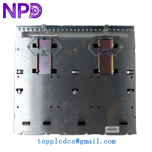
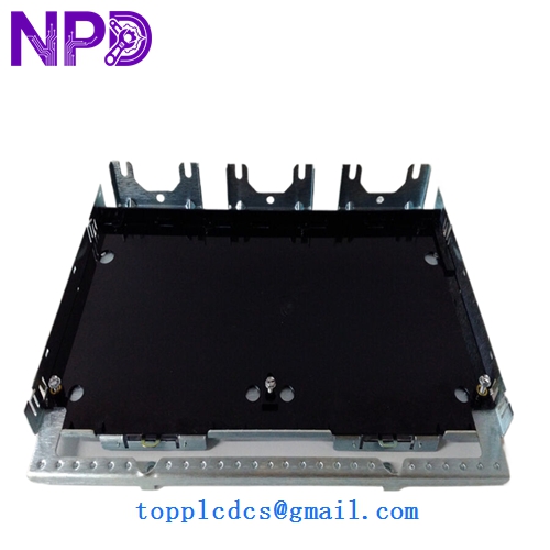
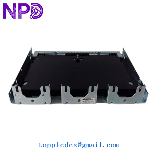
- Dimensions: 6.25 in x 7.0 in x 1.1 in (15.9 cm x 17.8 cm x 2.8 cm) The GE IS230TVBAH2A is a specialized termination board within the Mark VIe system dedicated to turbine vibration monitoring and machinery protection. It provides the physical landing points for 14 high-speed vibration sensors, including proximity probes and seismic transducers, as well as a dedicated Keyphasor input for phase-angle and RPM measurements. This board works in conjunction with the PVIB I/O pack to provide real-time hardware-level analysis of shaft vibration, axial position, and shell expansion, ensuring the turbine remains within safe mechanical limits and providing critical data for predictive maintenance.
Model Comparison
The IS230TVBAH2A represents the “H2A” revision, which features enhanced signal conditioning and improved isolation compared to the earlier IS230TVBAH1A. While both boards support the same channel count, the H2A version is better optimized for newer high-sensitivity accelerometers and offers more robust transient protection for the Keyphasor circuit. Compared to the legacy IS200VVIBH1A (used in Mark VI V-racks), the IS230TVBAH2A is a compact, DIN-rail mounted “S-style” board designed for the modern Mark VIe modular architecture, allowing for significantly easier field wiring and cabinet space optimization.
Operation Tips
- Transducer Power: Verify the jumper settings for each channel to ensure the board is providing the correct excitation voltage (e.g., -24V DC for standard Bently Nevada proximity probes).
- Keyphasor Alignment: Ensure the Keyphasor sensor is correctly gapped; a weak or noisy signal on this input will prevent the system from calculating phase-dependent vibration data (1X, 2X, etc.).
- BNC Test Points: Use the integrated BNC connectors on the front of the board to connect an external vibration analyzer or oscilloscope for live signal troubleshooting without disturbing field wiring.
- Shielding Continuity: Vibration signals are extremely low-voltage and susceptible to noise; ensure all sensor shields are grounded at the TVBA board and that no “pigtails” are created, as these can act as antennas for EMI.